10
Instruction Booklet IB02402001E
December 2010
Instructions for the Eaton Type
MPCV Network Protection Relay
EATON CORPORATION www.eaton.com
For more information visit: www.EatonElectrical.com IB02402001E
Instruction Bulletin
Page 10 Effective: September 2004
Instruction for the
Cutler-Hammer Type MPCV
Network Protection Relay
Instructions for the Type MPCV-GE Relay Used
on Type MG-8, MG-9, MG-14 AND MG-14A
Network Protectors
GE Relay Installation (General)
The MPCV-GE Relay is mounted onto the swinging cam-in
type stationary terminal assembly that previously held the
electromechanical Type CAN or CHN master relay.
The list below summarizes the wiring changes that are
necessary in order to adapt the MPCV Relay to GE Network
Protectors manufactured before October, 1982.
1. Pin 4 of the master relay socket must be wired to a pro-
tector ground. On some protectors, pin 4 of the master
relay socket is wired to an auxiliary transformer. Remove
this wire and provide a ground connection pin 4.
2. On the CAL or CHL phasing relay position, wires 6 and 6A
must be connected together. The best way to do this is
to remove wire 6A from the terminal strip and to connect
to the wire 6 position.
3. If the MPCV is being installed on protectors having
watt-var control, the existing watt-var circuitry must be
disabled. Follow the instructions given in Note 3 of the
watt-var installation notes.
4.
If the network protector is equipped with the old style time
delay relays, this circuitry should be disabled. Follow instruc-
tions given in Note 1 of the time delay installation notes.
For General Electric Network Protectors manufactured after
October, 1982, the Type CAN or CHN master relay was
replaced by the Type SSNPR analog, solid-state relay and
the above four wiring changes will have been made.
Once the MPCV-GE Relay has been installed and all of the
wiring changes have been performed and/or confirmed,
proceed to Section II of the MPCV-D instructions to complete
the calibration. Refer to Page 8.
Table 4. Terminal Configurations
Figure 4. GE Relay
Note: For communication with General Electric style relays.
Status input always uses AUX 1 which requires that a
breaker “b” contact is connected across points 7 and 8 of the
AUX I/O ports. This is required for monitoring the network
protector’s position (open or close).
Used as Communicating Relay
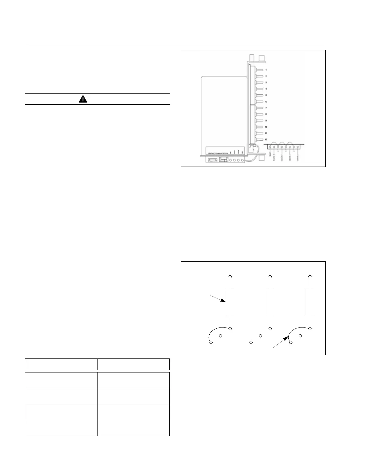
When applying PowerNet or IMPACC communications to
MPCV-GE Relay, it is important to jumper the Phase A and
Phase C phasing resistors to ensure that the metered voltages
are correctly monitored. Refer to Figure 5 below. Whether
the jumpers are installed or not, the relay’s protective func-
tions are not impaired.
Figure 5. Jumper Phase A and Phase C Resistors
WARNING
BEFORE PROCEEDING FURTHER, MAKE CERTAIN THAT THE
NETWORK PROTECTOR IS DE-ENERGIZED AND IS REMOVED
FROM ITS ENCLOSURE AND WITHDRAWN OUT ON THE
HOUSING EXTENSION RAILS.
SPECIFIC INSTRUCTIONS FOR PERFORMING THESE TASKS
ARE CONTAINED IN THE INSTRUCTION BOOK FOR THE
DIFFERENT GENERAL ELECTRIC DESIGNS. THOSE
INSTRUCTIONS MUST BE CONSULTED AND FOLLOWED.
Terminal
Number
Input to
MPCV-GE
1
2
3
Trip
Close
Common
4
5
6
Gnd
Van
Vcn
7
8
9
Vbn
N/A
Ia
10
11
12
Ic
Ib
Icom
13 23 33
16
19
14
36
39
34
Phasing
Resistors
Jumper
 Loading...


