23
Instruction Booklet IB02402001E
December 2010
Instructions for the Eaton Type
MPCV Network Protection Relay
EATON CORPORATION www.eaton.com
IB02402001E For more information visit: www.EatonElectrical.com
Instruction Bulletin
Effective: September 2004 Page 23
Instruction for the
Cutler-Hammer Type MPCV
Network Protection Relay
Installation Rules
In order to deliver a comprehensive and powerful
energy management solution for use in electrical distribu-
tion environments while ensuring affordability, flexibility,
simplicity and noise immunity the following rules will allow
the user to achieve the above advantages. These rules
are expected to be followed as a starting point before
troubleshooting is performed on a system.
1. Cable Selection
The approved cable types are:
■ Any of the cable in the Belden 9463 family.
■ IMPACABLE — a 600 volt rated custom designed for
IMPACC Style No. 2A95705G01.
2. Cable Intermixing
Any of the above approved cables may be intermixed
without compromising communication performance.
3. System Topology, Size and Capacity
Topology
■ Bus or single star.
■ Maximum number of long line from star: 5.
■ No line termination for tap.
■ Required EOLTR (100 ohms) at the end of long line.
■ Maximum cable length between ends of longest lines:
10,000 feet (3,048 m)
Attenuation:
■ Total system attenuation capacity: 25 dB.
■ Attenuation per device: 0.01 dB.
■ Attenuation of approved cables:
■ Attenuation at Star:
Definition
STAR — single point with a number of long lines
emanating from it.
LONG LINE — greater than 200-foot (61 m) wire run.
4. Cable Splicing
The prime goal is to create a secure electrical connection
while minimizing exposure to electrical transients.
■ Ferrules are used to dress cable ends in order to avoid
problems associated with frayed and loose wires.
■ Use the device built-in two pole terminal blocks when
splicing.
■ All devices, EOLTR, Simple Taps and Complex Taps
should be placed in parallel across the cable.
5. Cable Shielding
■ Cable shielding and outer jacket should not be stripped
longer than 1-1/2 inches (38.1 mm).
■ Use the three pole terminal blocks at tap points to ensure
a continuous metallic shield ground path.
■ Mechanically crimp sleeves on to the two-shield path
drain wires
■ The cable shield ground path for a Main Network and
Subnetwork must not be joined together. Each should
have a separate connection to earth ground reference.
6. Cable Grounding
■ The shield ground path of a Main Network (and each
subnetwork) should be broken up into two separate
isolated segments in such a way that a single, solid earth
ground is available within 3,000 feet (914.4 m) of any point
along the Main Network (or subnetwork).
■ Do not tie together drain wires of neighboring segments
to achieve isolation.
■ Insulate unused drain wire to prevent accidental
grounding.
■ Connect the shield ground path’s drain wire to a #14
AWG or larger multi-stranded wire that has an impedance
path of 1 ohm or less to a known earth ground. Note that a
new ground path will be required when the shield ground
travel through many connections and considerable
distances before reaching earth ground.
7. Cable Termination
The Main Runs of the Main network and each Subnetwork
require a pair of EOLTR, rated 100 ohms, _ watt carbon or
metal film resistors. Do not use wirewound resistors.
■ The resistors should be placed in parallel across the
splicing junction servicing the Complex Tap rather than
at the far end within the Complex Tap.
■ Tap off from the Main Runs do not require EOLTR.
8. Device Address
To avoid the possibility of devices in a Main Network having
the same address as those in Subnetworks, set the Main
Network device addresses to start at 100 or higher excluding
901 to 908.
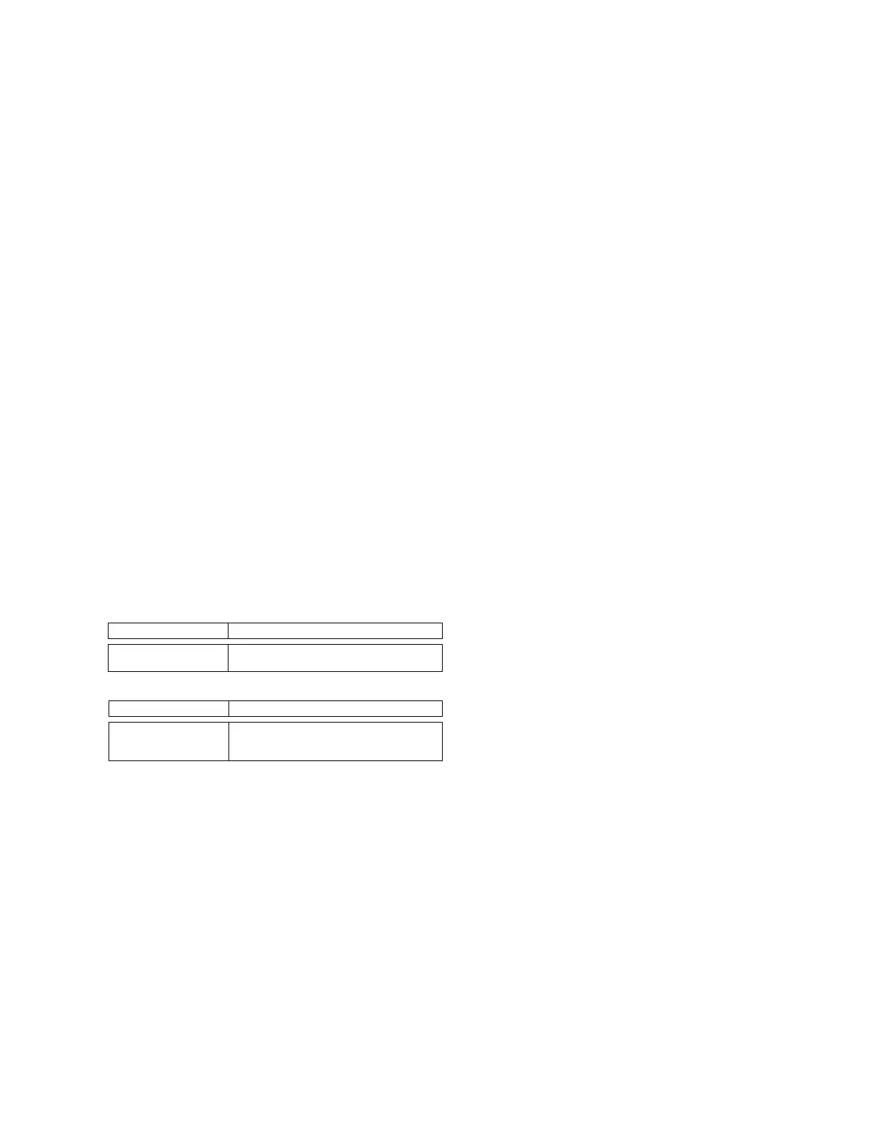
Cable Type Attenuation per 1,000 ft. (304.8 m)
IMPACABLE
Belden 9463
1.6 dB
2.0 dB
No. of Long Lines Attenuation
3
4
5
3.5 dB
6.0 dB
8.0 dB
 Loading...


