9
Instruction Booklet IB02402001E
December 2010
Instructions for the Eaton Type
MPCV Network Protection Relay
EATON CORPORATION www.eaton.com
IB02402001E For more information visit: www.EatonElectrical.com
Instruction Bulletin
Effective: September 2004 Page 9
Instruction for the
Cutler-Hammer Type MPCV
Network Protection Relay
Instructions for the Type MPCV-22 Relay Used on
a Type CM-22, 216 Volt, Network Protector
Note: Also applicable to the Type MPCV-22 Relays supplied on Type
CMR Network Protectors.
Installation (General)
A. Remove the CN-33 master relay and the CNJ phasing
relay, as well as the BN relay. Install a BN dummy or jack
plate if a BN relay was removed. If there is no BN relay,
but the position is taken by a BN dummy plate or BN jack
plate. DO NOT REMOVE THE BN DUMMY OR
JACK PLATE.
B. Install Style No. 508B559G01 phasing jumper plate in
the location of the CNJ phasing relay.
C. Install the Type MPCV-22 Relay, Style No. 6417C83G01,
in location of the CN-33 master relay. If the network pro-
tector is wired for an electromechanical watt-var relay,
the wiring must be changed over to the watt tip charac-
teristic. Refer to I.B. 35-552, Pages 36 – 37. The MPCV
can be set for a watt or watt-var trip characteristic.
Although its input is connected as a watt characteristic,
the change to watt-var is accomplished by changing the
“WV” set point from OFF to ON.
D. Proceed to Section II of the MPCV-D instructions
(calibration section). Refer to Page 8.
Note: For CM-22 or CMR breakers which have been rewired to accept
the MPCV, phase 4 or phase 5 relay, the Type MPCV-2X is a direct
replacement. Style Number is 6417C83G03.
Table 3. Terminal Configurations
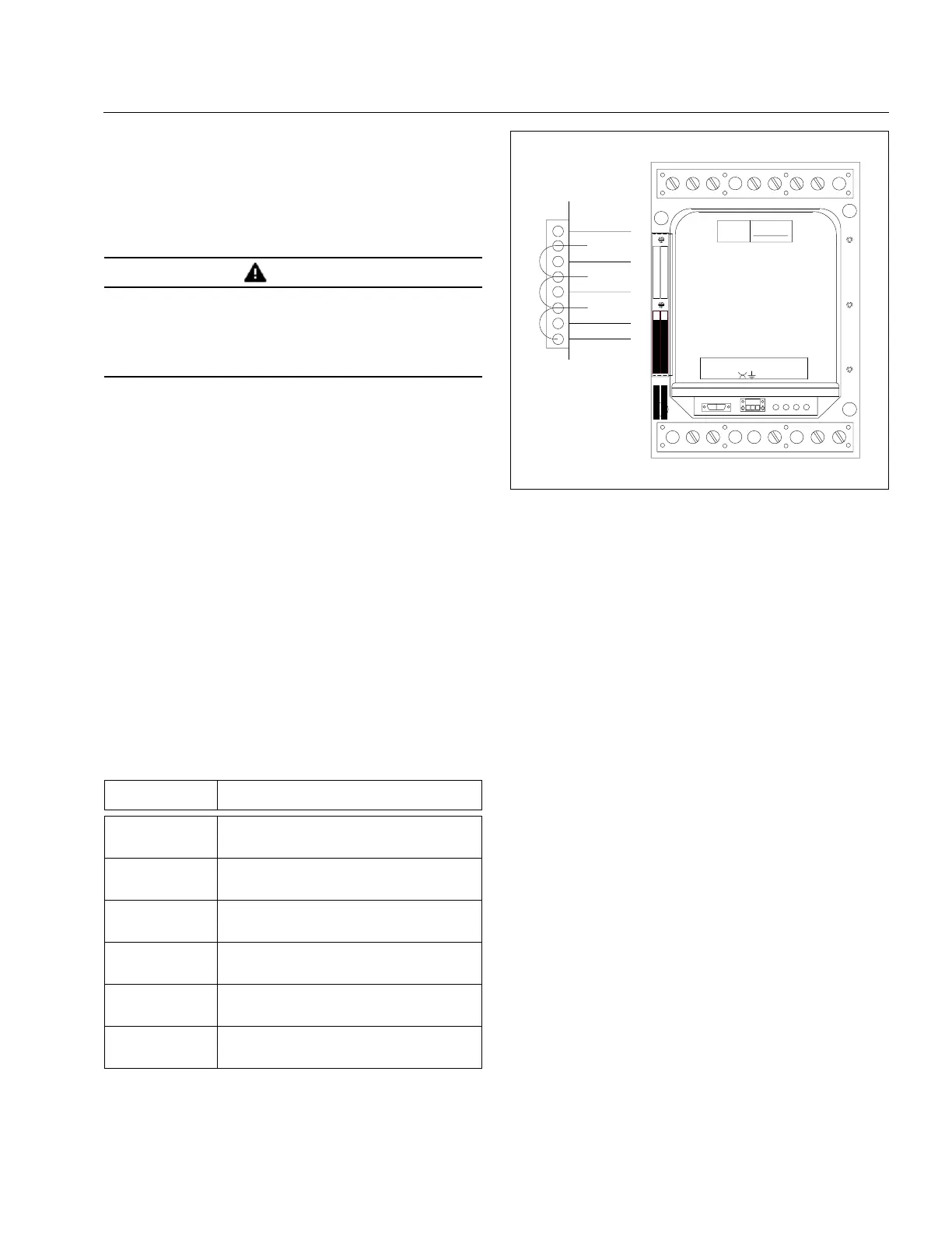
Figure 3. Cutler-Hammer Relay
Note: For Communication with Cutler-Hammer style relays.
Status input always uses AUX 1, which requires that a
breaker “b” contact is connected across points 7 and 8 of the
AUX I/O ports. This is required for monitoring the network
protector’s position (open or close).
WARNING
BEFORE PROCEEDING FURTHER, MAKE CERTAIN THAT THE
NETWORK PROTECTOR IS DE-ENERGIZED AND IS WITHDRAWN
FROM THE ENCLOSURE ON THE EXTENSION RAILS. SPECIFIC
INSTRUCTIONS FOR PERFORMING THESE TASKS ARE
CONTAINED IN INSTRUCTION BOOK I.B. 35-500-1C. THOSE
INSTRUCTIONS MUST BE CONSULTED AND FOLLOWED.
Terminal
Number
Input to MPCV-D,
22 or 2x
1
2
3
Common
Trip
Close
4
5
6
N/A
Ground
“A” Phase network side voltage
7
8
9
“A” Phase transformer side voltage
“A” Phase current
N/A
10
11
12
N/A
“C” Phase current
“C” Phase transformer side voltage
13
14
15
“C” Phase network side voltage
N/A
“B” Phase current
16
17
18
N/A (Internally tied to point 5)
“B” Phase transformer side voltage
“B” Phase network side voltage
COMMUNICATIONS
PENDANT
FLOAT
FAIL
CLOSE
TRIP
IMPACC
ADDRESS
1 2 3 4 5 6 7 8 9
Aux. I/O
Configuration
1 (GND)
2 (AUX4)
3
4 (AUX3)
5
6 (AUX2)
7
8 (AUX1)
10 11 12 13 14 15 16 17 18
 Loading...


