8
Instruction Booklet IB02402001E
December 2010
Instructions for the Eaton Type
MPCV Network Protection Relay
EATON CORPORATION www.eaton.com
For more information visit: www.EatonElectrical.com IB02402001E
Instruction Bulletin
Page 8 Effective: September 2004
Instruction for the
Cutler-Hammer Type MPCV
Network Protection Relay
Instructions for the Type MPCV-D Relay used on
Type CMD, 216 Volt, Network Protectors
I. Installation
a. Remove the CN-33 master relay and the CNJ phasing
relay, as well as the BN relay. Install a BN dummy or
jack plate if a BN relay was removed. If there is no BN
relay, but the position is taken by a BN dummy plate
or BN jack plate. DO NOT REMOVE THE BN DUMMY
OR JACK PLATE.
b. Install Style No. 508B559G01 phasing jumper plate in
the location of the CNJ phasing relay.
c. Install the Type “MPCV”, Style No. 6417C82G01, in
location of the CN-33 master relay.
If the network protector is wired for an electromechanical
watt-var relay, the wiring must be changed over to the watt
trip characteristic. Refer to l.B. 35-552, Pages 36 – 37. The
MPCV can be set for a watt or watt-var trip characteristic.
Although its input is connected as a watt characteristic, the
change to watt-var is accomplished by changing the “WV”
set point from OFF to ON.
II. Calibration
a. Connect a network protector portable test kit to the
network protector. Specific instructions for performing
this task are contained in I.B 35-556.
b. Power-up the test kit in the relay test mode. Set the
test kit to zero phasing volts, either in phase or at 60
degrees. Once the test set is powered with zero phas-
ing volts, (the Variac set to zero), the MPCV Relay will
advance to float. This indicates that the power-up
mode of the relay is correct. Connect the setting
pendant to the relay, by plugging the setting pendant
into the exposed 9 pin “D” connector.
Note: Note the connector and plug are polarized to prevent improper
connection.
c. De-press the EDIT key to begin the “Edit” mode.
Note: At this point, the amber float light will begin to flash and the
first set point, with its loaded value, will appear on the display of the
pendant. While in this mode, the relay will not change state and is
effectively inoperable for normal relay functions.
d. To change a set point, de-press the large or small,
up or down arrow keys for large or small increment
adjustments until the desired value appears on the dis-
play.
e. Once the desired value is obtained, de-press the NEXT
key. The program will automatically step to the next
set point to be set.
f. Continue to adjust each set point by repeating Steps d
and e above until all the set points have been
satisfied.
Note: The starting set point is HZ=60. Refer to the settings on Page 5.
Note: When setting the master line values on a 216 volt relay being
used on a 480 volt system, the phasing voltage necessary to close
the relay is not directly indicated. The relay calibration on this
system is determined by multiplying the master line setting by 2.2.
Refer to Table 2.
Table 2. Overvoltage Close Values for 480 Volt Units Using Potential
Transformers
Approximate phasing volts required to close the relay
contacts, in phase, equals 2.2 times the “MPC” relay setting,
Note: If the BN time delay is not required, make certain that the time
delay is set to zero (TD=0).
g. Once ALL the set points have been set, de-press the
SAVE key. The display will go blank and the float light
will remain constantly ON.
Note: If changing only one or two of the set points, the entire menu
need not be reviewed prior to de-pressing the SAVE key.
h. Remove the pendant from the relay; the relay
calibration is now complete.
Note: On all 216 volt units, the master line (ML) value equals the
phasing volts required to close the relay contacts, in phase.
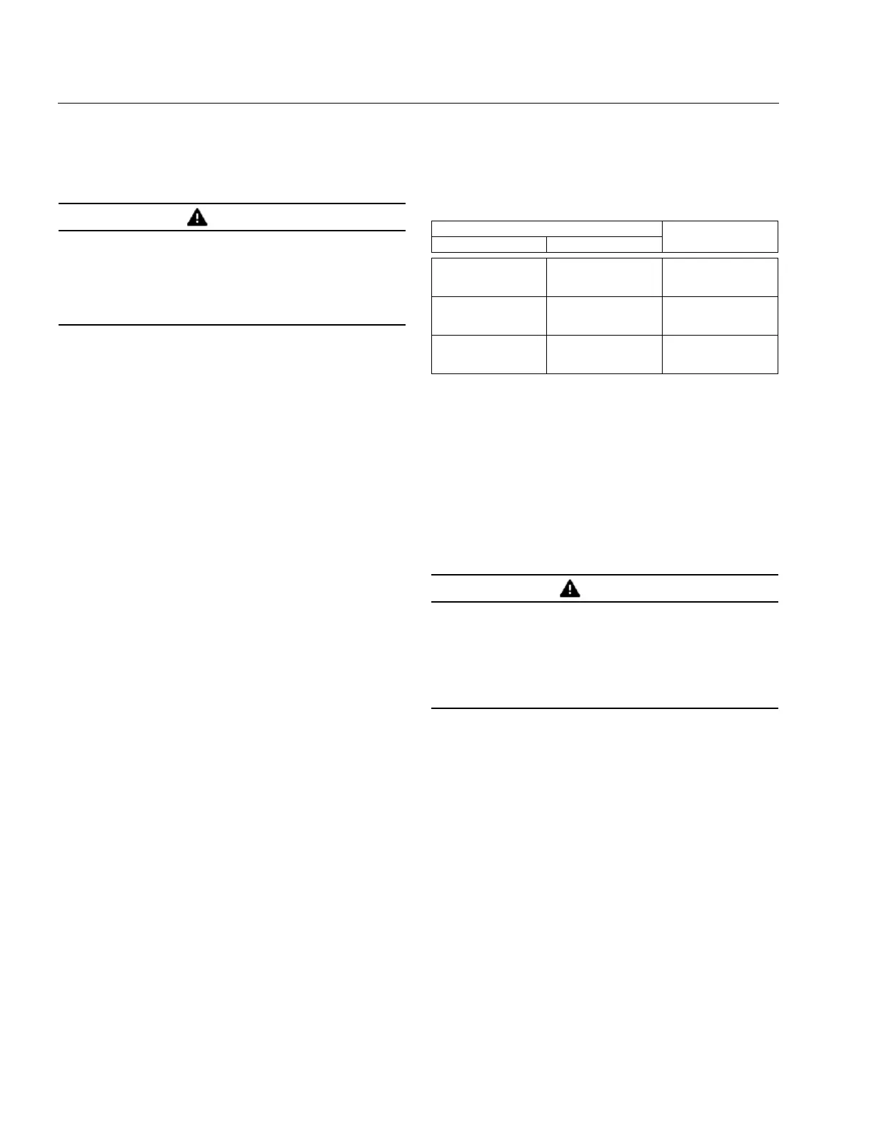
WARNING
BEFORE PROCEEDING FURTHER, MAKE CERTAIN THAT THE
NETWORK PROTECTOR IS DE-ENERGIZED AND IS
WITHDRAWN FROM THE ENCLOSURE ON THE EXTENSION
RAILS. SPECIFIC INSTRUCTIONS FOR PERFORMING THESE
TASKS ARE CONTAINED IN THE LATEST REVISION OF
INSTRUCTION BOOK 1.B. 35-552. THOSE INSTRUCTIONS
MUST BE CONSULTED AND FOLLOWED.
Overvoltage Close Value Desired Master Line (ML)
Setting
At 60 Degrees In Phase
.70 V
1.45 V
2.13 V
.45 V
.90 V
1.32 V
ML = .20
ML = .40
ML = .60
2.85 V
3.55 V
4.28 V
1.75 V
2.20 V
2.60 V
ML = .80
ML = 1.00
ML = 1.20
5.00 V
5.70 V
6.40 V
3.05 V
3.50 V
4.00 V
ML = 1.40
ML = 1.60
ML = 1.80
WARNING
DO NOT FUNCTIONALLY OPERATE (TRIP AND CLOSE) THE
NETWORK PROTECTOR BREAKER WITH THE SETTING
PENDANT CONNECTED INTO THE RS-232 PORT.
CALIBRATION OF THE MPCV MUST BE MADE WITH THREE-
PHASE POTENTIAL AND ONLY AFTER THE FLOAT LIGHT IS
ILLUMINATED. AT THE END OF THE CALIBRATION
SEQUENCE, THE PENDANT MUST BE REMOVED PRIOR TO
OPERATION OF THE BREAKER.
 Loading...


