6.1.11 MTL4516C - Switch/Proximity detector interface
Two channel, with line-fault detection and phase reversal - changeover contacts
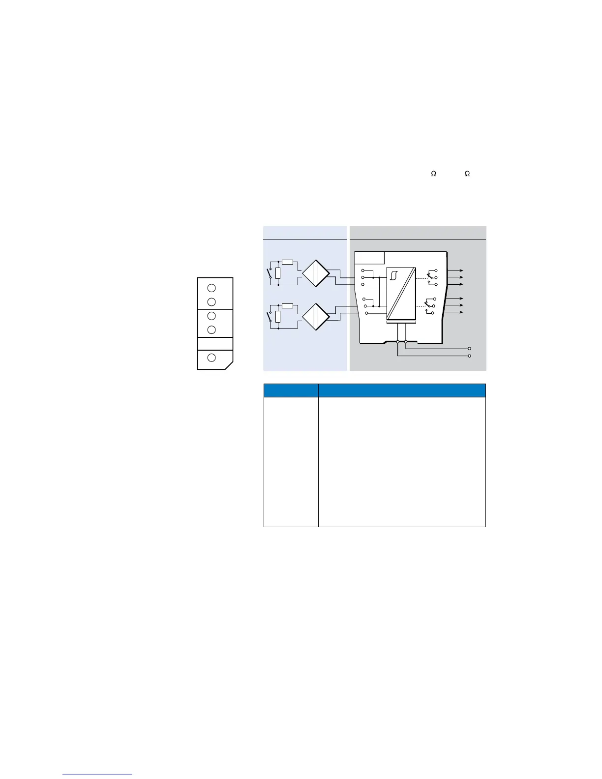
The MTL4516C contains two changeover relays, which enable two safe-area loads to
be controlled by switches or proximity detectors located in a hazardous-area. When
selected, the line-fault detect (LFD) facility detects open or short circuit conditions in the
field wiring and also indicates this on the top of the module. Line-Fault Detect and Phase
Reversal for the channel are selected by DIL switches on the side of the module and
output is provided by the changeover relay contacts.
See page 15 for LFD and PR switch details. Channel 1 & 2 switch settings apply..
For switch sensor inputs, with LFD selected, make sure resistors (22k
and 680 ) are fitted.
Note: For reliable, long-term operation the load on the output switching relays should not
be less than 50mW, e.g.10mA at 5VDC.
Terminal Funct ion
1 Input –ve (Ch 1)
2 Input +ve (Ch 1)
4 Input –ve (Ch 2)
5 Input +ve (Ch 2)
7 Normally-open contact (Ch 1)
8 Common (Ch 1)
9 Normally-closed contact (Ch 1)
10 Normally-open contact (Ch 2)
11 Common (Ch 2)
12 Normally-closed contact (Ch 2)
13 Supply –ve
14 Supply +ve
Hazardous area Safe area
+
–
+
–
Ch 2
Ch 1
22kΩ
680Ω
22kΩ
680Ω
Vs–
Vs+
20 to 35V dc
Switch-type sensors
require resistors
if LFD is selected
6
5
4
3
2
1
9
8
7
12
11
10
13
14
Figure 6.11:
Top label for
MTL4516C
 Loading...