8.3 Analogue Input (AI) Modules
All of these tests compare the output current with the input current (A1) over the normal
range of operation, and measure the “error current” i.e. the difference - as indicated on A2.
Apply these tests per channel, as appropriate.
Ammeter A2 must be capable of handling either polarity. If it is not an auto-ranging
instrument, set it to a high range before switch on, then adjust sensitivity to obtain the
required reading.
8.3.1 Modules: MTL4541,
MTL4541B/P/T, MTL4541Y,
MTL4544, MTL4544B &
MTL45544D
Output Measurements
Note: Do not connect a voltmeter in circuit to measure V1 until requested in Step 4 below,
because current measurement A2 could be affected.
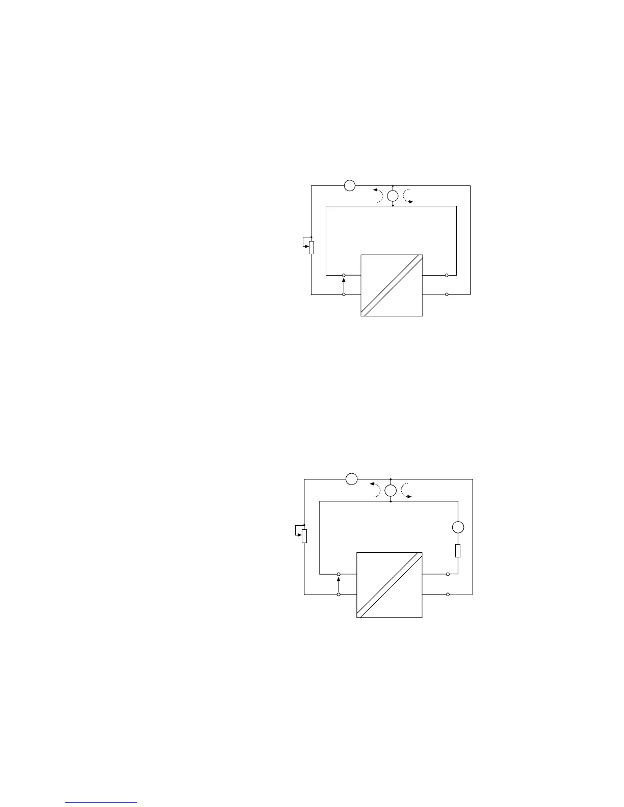
1. Adjust RV1 to vary the current (A1) through the range 4 to 20mA
2. The measured current imbalance (A2) over this range should not exceed ± 20µA
3. Adjust RV1 for a 20mA reading on A1
4. The voltage V1, across the channel input, should typically be >16.5V.
8.3.2 Modules: MTL4541S, MTL4544S & MTL4561
+
–
+
–
V1
i/p
o/p
RV1
10kΩ lin.
A1
250Ω
24V
+
–
I
o
I
i
A2
+
–
Output Measurements
Note: Do not connect a voltmeter in circuit to measure V1 until requested in Step 4 below,
because current measurement A2 could be affected. Set A2 range to
1. Adjust RV1 to vary the current (A1) through the range 4 to 20mA.
2. The measured current imbalance (A2) over this range for the MTL4541S and the
MTL4544S should not exceed ± 20µA. For the MTL4561 the imbalance should not
exceed ± 400µA.
3. Adjust RV1 for a 20mA reading on A1
4. The voltage V1, across the channel input, should typically be >16.5V.
Figure 8.5:
AI test circuit #1
Figure 8.6:
AI test circuit #2
“o/p sinking”
 Loading...