6.2.8 MTL4526 - Switch operated relay
Two channel, IS output
The MTL4526 enables two separate IS circuits in a hazardous area to be relay-contact
controlled by two on-off switches or logic signals in a safe area. Applications include
the calibration of strain-gauge bridges; changing the polarity (and thereby the tone) of
an IS sounder; the testing of IS fire alarms; and the transfer of safe-area signals into an
annunciator with IS input terminals not segregated from each other. The output-relay
contacts are certified as non-energy-storing apparatus, and can be connected to any IS
circuit without further certification, provided that separate IS circuits are such that they
would remain safe if connected together.
Mode Function SW1 SW2 SW3 SW4
Contact/
Logic
Input
2 ch Off On On On
1in2out On On On On
Loop Powered
2 ch Off Off Off Off
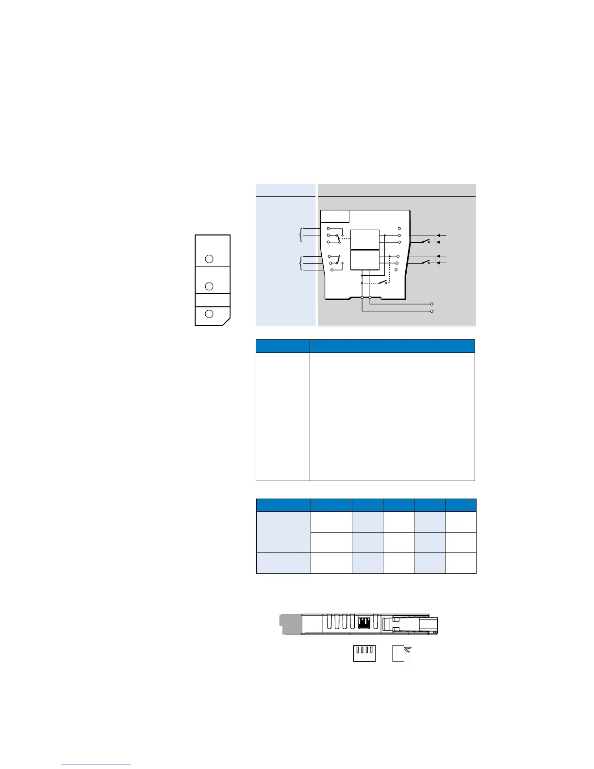
Terminal Function
1 IS relay output 1 (normally open)
2 IS relay output 1 (normally closed)
3 IS relay output 1 (common)
4 IS relay output 2 (common)
5 IS relay output 2 (normally closed)
6 IS relay output 2 (normally open)
8 Relay 1 control +ve
9 Relay 1 control –ve
10 Relay 2 control +ve
11 Relay 2 control –ve
13 Supply –ve
14 Supply +ve
Hazardous area Safe area
1
2
3
4
5
6
IS relay
IS relay
1
2
+
–
+
–
All contacts shown
in normal position
(relays de-energised)
Vs–
Vs+
20 to 35V dc
+
–
+
–
Control
20 to
35V dc
Loop
powered
Contact
inputs
9
8
7
12
11
10
1
2
Sw4
13
14
OFF position
ON position
1 2 3 4
Figure 6.20:
Top label for
MTL4526
Table 6.3 Switch settings for modes
 Loading...