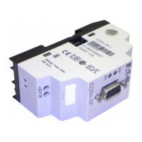
8.3.6 Module: MTL4581
Note: V1 should be capable of measurement to within 1µV.
Output Measurements
1. With the LINK connected, vary output V2 between 0 and 50mV using RV1. V1 should
show <50µV variation. (Note: Safety Drive can be ON or OFF )
2. With the LINK disconnected and Safety Drive ON, V2 should drive to >+50mV with the
switch set to ‘+’, or <–50mV with the switch set to ‘–’.
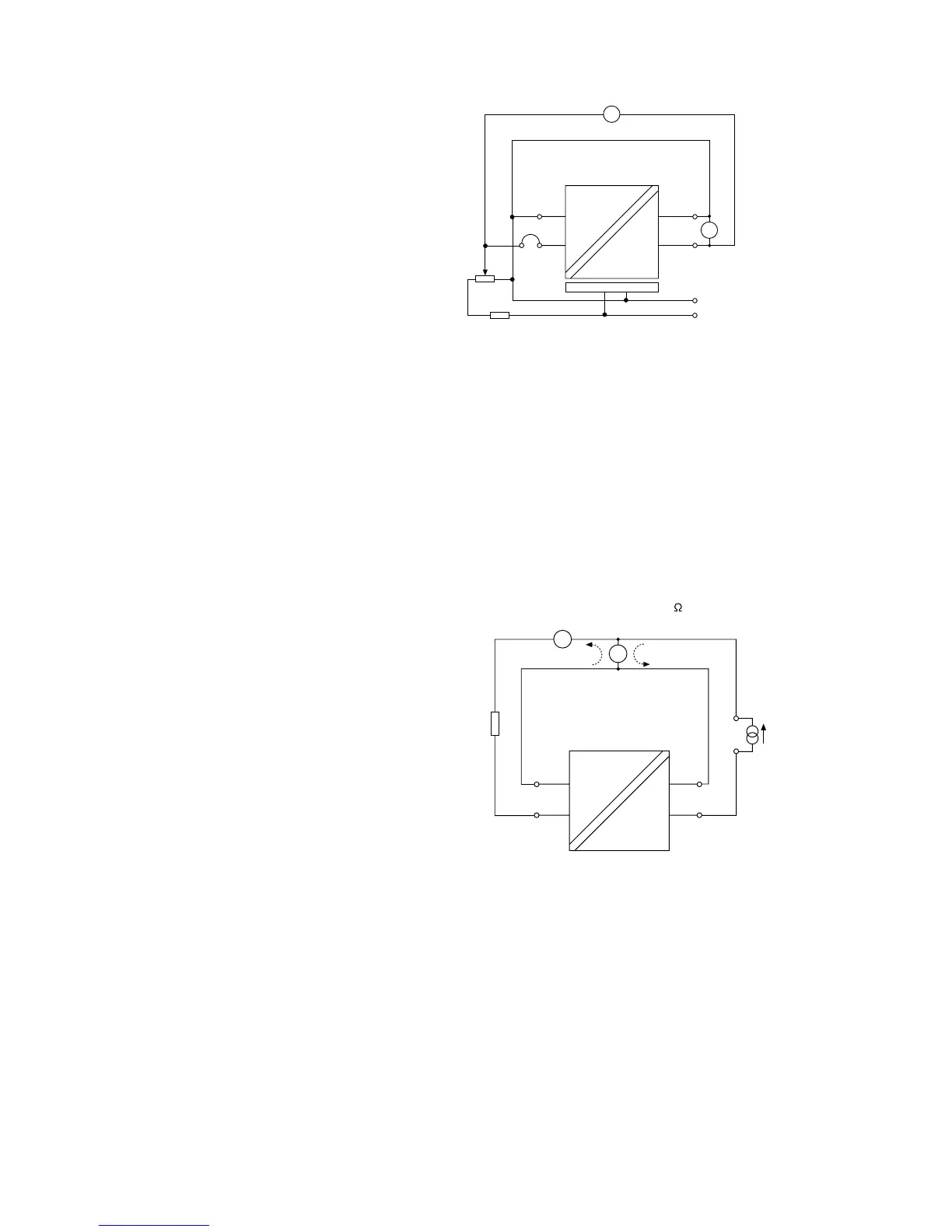
8.4 Analogue Output (AO) Modules
The test compares the output current with the input current over the normal range of
operation.
8.4.1 Modules: All variants
Input Conditions
The chosen “load” resistor can be any value between 100 and 800
.
+
–
+
–
A2
+
–
A1
o/p i/p
current
source
–
470Ω
load
I
o
I
i
Output Measurements
1. Adjust the current source to vary the current (A1) through the range 4 to 20mA.
2. The measured current imbalance (A2) over this range should not exceed ± 20µA.
8.5 Testing the functioning of other modules
Simple tests to verify their basic operation can be devised for other modules (e.g.
temperature, pulse, vibration, etc). If any assistance is required for the testing of a particular
module, please contact the technical support department at Eaton for advice.
Figure 8.9:
AI test circuit #5
“mV input”
Figure 8.10:
AO test circuit
 Loading...