MN04002001E
1
March 2006
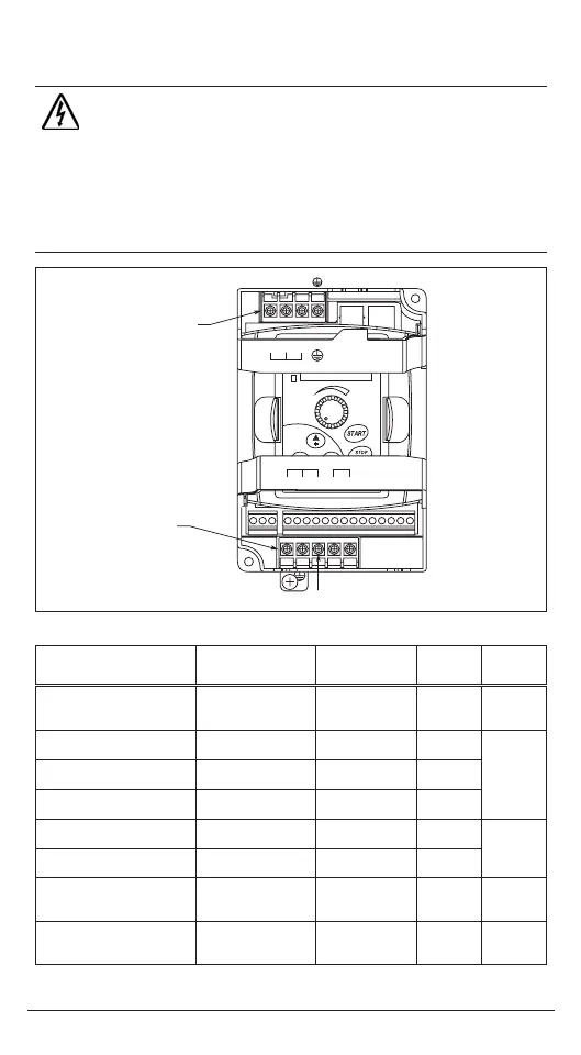
Step 1 — Wiring
azar
ous
g
o
tage
Wire Type: 75ºC Copper Only
HIGH VOLTAGE!
Motor control equipment and electronic controllers are connected to
hazardous line voltages. When servicing drives and electronic
controllers, there may be exposed components with housings or
protrusions at or above line potential. Extreme care should be taken to
protect against shock.
For the best results with the MVX9000 inverter, carefully read the
manual and all of the warning labels attached to the inverter before
installing and operating it, and follow the instructions exactly.
Catalog Number
Voltage
Horsepower
Max. Current (A)
(Input/Output)
Wire
Gauge
(AWG)
Torque
Rating
(kgf-cm)
MVXF25A0-1 (1-phase)
MVXF50A0-1 (1-phase)
MVX001A0-1 (1-phase)
115V AC, 1/4 hp
115V AC, 1/2 hp
115V AC, 1 hp
6/1.6
9/2.5
16/4.2
12 – 14
12 – 14
12
14
MVXF50A0-2 (1-phase)
MVXF50A0-2 (3-phase)
240V AC, 1/2 hp
240V AC, 1/2 hp
6.3/2.5
3.2/2.5
12 – 14
12 – 14
14
MVX001A0-2 (1-phase)
MVX001A0-2 (3-phase)
240V AC, 1 hp
240V AC, 1 hp
11.5/5
6.3/5
12 – 14
12 – 14
MVX002A0-2 (1-phase)
MVX002A0-2 (3-phase)
240V AC, 2 hp
240V AC, 2 hp
15.7/7
9/7
12
12 – 14
MVX003A0-2 (1-phase)
MVX003A0-2 (3-phase)
240V AC, 3 hp
240V AC, 3 hp
27/10
15/10
8
8 – 12
15
MVX005A0-2
MVX007A0-2
240V AC, 5 hp
240V AC, 7-1/2 hp
19.6/17
28/25
8 – 10
8
MVX001A0-4
MVX002A0-4
MVX003A0-4
480V AC, 1 hp
480V AC, 2 hp
480V AC, 3 hp
4.2/3
5.6/4
6/5
12 – 14
12 – 14
12 – 14
14
MVX005A0-4
MVX007A0-4
MVX010A0-4
480V AC, 5 hp
480V AC, 7-1/2 hp
480V AC, 10 hp
8.5/8.2
14/13
23/18
8 – 14
8 – 12
8 – 10
15
T1 T2
MOTOR Braking
LINE
T3 B1 B2
T1
T2 T3
B1
B2
L1 L2 L3
L1 L2
L3
Motor
Connections
Line
Connections
MN04002001E.fm Page 1 Thursday, April 13, 2006 11:11 AM

 Loading...


