PROFIBUS-DPV0 functions
103
11/04 MN01219002Z-EN
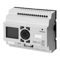
The inputs 1 to 3 of the DMI can be connected with switches
or pushbuttons to the local control of the motor to suit the
selected motor-starter function ( a section “Motor
starter”, Page 44). Input 4 and 5 are intended for connection
of the auxiliary switch, in order to recognise the switching
state of the circuit-breaker.
Bit 3 Input 4
Bit 4 Input 5
Bit 5 to Bit 7 Not used
Octet 12
Bit 0 Not used
Bit 1
Motor state
Bit 2 and Bit 3 Not used
Bit 4 Motor “ON” or motor anticlockwise
rotation
Bit 5
Motor clockwise rotation
Bit 6 Star configuration
Bit 7
Delta configuration
Data position Designation
h
When accessing the phase currents I
1
to I
3
and I
max
,
please note the Motorola coding format (Octet N: High-
Byte, Octet N+1: Low-Byte) used in PROFIBUS-DP for data
in WORD format. If the data processing format in your DP
master system deviates from this standard, and the DP
access commands do not automatically include a
conversion, it will be necessary to implement and perform
the conversion in your application program. Please refer to
the documentation of your DP master system.
Artisan Technology Group - Quality Instrumentation ... Guaranteed | (888) 88-SOURCE | www.artisantg.com

 Loading...


