Installation
4 S611 Soft Starter MN03901003E—January 2012 www.eaton.com
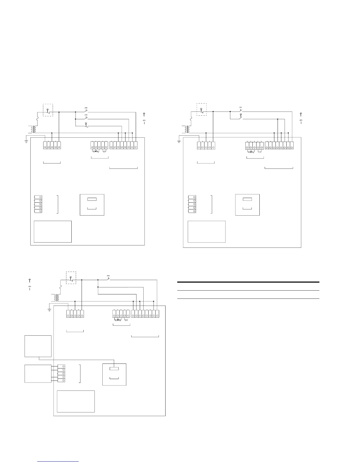
Typical Control Wiring Diagrams
For a single conductor, a minimum wire of 14 AWG (2.5 mm
2
) should be used between the
control power transformer and the supply terminals.
Basic Connection Diagram for 120 Vac Three-Wire
Pushbutton
Basic Connection Diagram for 120 Vac Network Control
Basic Connection Diagram for 120 Vac Two-Wire
Pushbutton
Terminal Block Wiring Capacity
Reset
E-Stop
Maintained
Momentary
Ground
+24V
D0
D1
Common
N–Tap
Neutral
L–Tap
Line
Start
Stop
TB1
120 Vac
Supply
User Interface
Module
TB4
Comms Port A
98 97 96 13 14
Comms Port B
TB5 (Connector)
TB2
Relays
TB3
120 Vac
Control
Relay 2 Relay 1
N–Network
L–Network
N–Permissive
L–Permissive
N–Start
L–Start
N–Reset
L–Reset
Reset
E-Stop
Maintained
Momentary
Comms Adapter
Comms
Modbus
TB4
DeviceNet
Modbus
PROFIBUS
TB5 (Module)
Ground
+24V
D0
D1
Common
N–Tap
Neutral
L–Tap
Line
Run Enable
Network
TB1
120 Vac
Supply
User Interface
Module
Comms Port B
TB5 (Connector)
TB4
Comms Port A
TB2
Relays
TB3
120 Vac
Control
98 97 96
13
14
N–Network
L–Network
N–Permissive
L–Permissive
L–Start
N–Startl
N–Reset
L–Reset
Relay 2 Relay 1
Wire Size
Number of
Conductors
Torque
Requirements
22–16 AWG (0.33–2.5 mm
2
) 2 3.5 lb-in (0.4 Nm)
14–12 AWG (4.0 mm
2
) 1 3.5 lb-in (0.4 Nm)
Maintained
Momentary
Reset
E-Stop
Start/Run
98 97 96 13 14
Ground
+24V
D0
D1
Common
N–Tap
Neutral
L–Tap
Line
TB1
120 Vac
Supply
User Interface
Module
TB4
Comms Port A
Comms Port B
TB5 (Connector)
TB2
Relays
TB3
120 Vac
Control
Relay 2 Relay 1
N–Network
L–Network
N–Permissive
L–Permissive
N–Start
L–Start
N–Reset
L–Reset
www.comoso.com

 Loading...