4
Instruction Booklet IB131006EN
Effective March 2019
Instructions for installation,
operation, and maintenance of type
VCP-W vacuum circuit breakers
EATON www.eaton.com
6. Inspection, maintenance, and troubleshooting ........................................... 48
6.1 Introduction ................................................................... 48
6.2 Frequency of inspection and maintenance ........................................... 48
6.2.1 Qualified personnel .......................................................... 48
6.2.2 General torque guidelines ..................................................... 49
6.3 Inspection and maintenance procedures ............................................. 50
6.4 Vacuum interrupter integrity test ................................................... 51
6.5 Contact erosion and wipe ........................................................ 51
6.6 Insulation ..................................................................... 53
6.7 Insulation integrity check ......................................................... 53
6.8 Primary circuit resistance check ................................................... 53
6.9 Mechanism check .............................................................. 53
6.9.1 CloSure™ test .............................................................. 53
6.10 Megger and power factor testing ................................................. 53
6.11 Mechanism lubrication .......................................................... 57
6.12 Finger clusters and switchgear stab lubrication ....................................... 57
6.13 Main contacts to switchgear primary engagement .................................... 57
6.14 How to determine the manufacturing date .......................................... 57
6.15 Troubleshooting chart ........................................................... 58
6.16 End of life procedures .......................................................... 58
6.17 Failure reporting ............................................................... 58
7. Renewal parts .................................................................... 59
7.1 General .......................................................................59
7.1.1 Ordering instructions ......................................................... 59
8. Optional accessories ............................................................... 70
8.1 Optional factory installed roll-on-floor wheel kit ....................................... 70
8.2 Optional automatic/manual hybrid secondary for BPI pan assembly ....................... 70
8.3 Optional 3,000 A ball screw drive for BPI pan assembly .................................71
List of figures
Figure Title Page
Figure 1. Type VCP-W, VCPW-SE, and VCP-WC circuit breaker outlines & dim. in inches (mm). ........ 11
Figure 2. Type VCPW-ND circuit breaker outlines and dimensions in inches (mm). ................. 12
Figure 3. Typical VCP-W tools and accessories. ............................................ 23
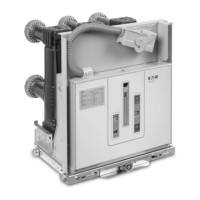
Figure 4. Typical front view VCP-W vacuum circuit breaker. ................................... 24
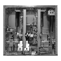
Figure 5. Typical VCP-W vacuum circuit breaker element with front cover removed. ................ 25
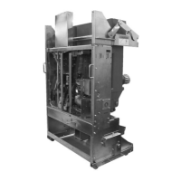
Figure 6. Typical rear view VCP-W vacuum circuit breaker element. .............................26
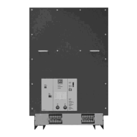
Figure 7. Typical VCP-W vacuum circuit breaker front cover arrangement. ........................ 27
Figure 8. Type VCP-W circuit breaker manual charging handle in use. ........................... 28
Figure 9. Insertion of the drawout extension rails. ..........................................29
Figure 10. Lifting and setting the breaker in the housing. ..................................... 29
Figure 11. Front panel. ................................................................ 30
Figure 12. BPI pan assembly. .......................................................... 31
Figure 13. Non-BPI pan assembly. ...................................................... 32
Figure 14. Engaging extension rails in a lower circuit breaker compartment. ..................... 34
Figure 15. Typical VCP-W circuit breaker bottom view. ....................................... 34
Figure 16. Pulling secondary disconnect cage to engage secondaries in TEST position. .............35
Figure 17. Engaging levering-in crank. .................................................... 35
Figure 18. Typical VCP-W rear view showing vacuum interrupters and current carrying system. ....... 36
Figure 19. Graphic representation of arc interruption. ....................................... 37
Figure 20. Closing cam and trip linkage. .................................................. 39
Figure 21. Charging schematic. .........................................................40
Figure 22. Typical VCP-W DC and AC control schemes. ...................................... 42
Figure 23. 15 kV VCP-WXC 63 kA 1200-3000 A special power plant breakers .................... 43
Figure 23. 5 kV VCP-WXC 63 kA 1200-3000 A special power plant breakers. ..................... 44
Figure 24. 15 kV under-voltage trip device configuration. .....................................46
Figure 25. Lubrication points. .......................................................... 49
 Loading...