EN
Operating and
maintenance manual
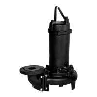
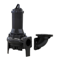
Submersible motor-driven pumps
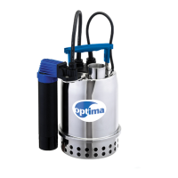
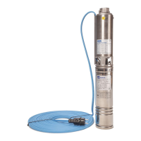
Serie BEST, RIGHT, DW
5.1. INSTALLATION (FIG.1-5)
To install the pumps, proceed as directed in PART 1, chapter
7.2 and in the following point:
rof )seires WD no sepip latem( sepip digir esu ot tseb si tI )a
permanent installations and exible pipes for temporary
installations, with sizes as given in chap. 4, observing the
distances illustrated.
5.2. INSTALLING DW PUMP WITH DN 50 FLANGE (FIG. 6-7)
-rus eht no tnuom eht netsaf ,swercs tnaveler eht gnisU )a
faces due to support the pump;
b) screw the delivery pipe onto the mount;
uoy hcihw gnola ediug a htiw dor a serutaef tnuom eht )c
slide the hook required to lower the pump;
-saf epor eht yb ti gnidloh ,pmup nevird-rotom eht rewol )d
tened around the handle, until the ange slots into place
on the mount;
sti
rednu tnuom eht htiw selpuoc pmup nevird-rotom eht )e
own weight.
6. STARTING
New pumps may feature a small amount of oil (the food
kind), which does not present a source of health risk.
6.1. VERSION WITH FLOAT (MA-MS) (SEE FIGURE)
Plug into the power mains and/or turn on with the switch:
the motor-driven pump starts working. Once the pump
has sucked in enough water to reach the minimum level
(“OFF” level), regulated by the oat, it will turn o auto-
matically.
The oat’s working position is factory set so as to assure a
minimum immersion level in the “OFF” position.
NB: If the liquid is overly contaminated, the operation of the
magnetic-type oat (MS versions) may be compromised,
meaning it needs to be cleaned on a regular basis.
Moreover, do not use in liquids polluted with iron dust or
magnetic material as this would compromise the operation
of the oat.
6.2. VERSION WITHOUT FLOAT
Plug into the power mains and/or turn
on with the switch:
the motor-driven pump starts working. Once the pump has
sucked in enough water to reach the minimum level, unplug
from the power mains and/or turn o with the switch.
6.3. RIGHT - DW PUMPS
fo gnisac pmup eht fo edis eht no eloh tnev a si erehT )a
RIGHT and DW versions for priming. During operation,
there will be a small recycling jet from it.
serutaef spmup WD eht fo noisrev esahp-eerht ehT )b
a 3-wire + earth power cord with the addition of two
white and grey wires with a smaller cross-section con-
nected to the thermal overload protector inside the mo-
tor (FIG. 13).
-fe na ot eriw neerg/wolley s’droc rewop eht tcennoC –
cient earthing system, which must be in compliance
with the regulations in force in the user’s country;
yb dedivorp lan
gis eht fo esu dna noitcetorp daolrevo –
the thermal overload protector are the user’s responsi-
bility;
-tengam-lamreht elbatius evah tsum stinu pirt daolrevo –
ic devices set appropriately for the motor-driven pump
installed;
tsum seriw yerg dna etihw owt eht ,rosnes taeh eht rof –
be connected to an electrical circuit that can cut power
to the motor-driven pump.
7. MAINTENANCE
To maintain the motor-driven pumps properly and ensure
their long service life, the lter and/or suction port must
not be clogged and the impeller must be clean.
During maintenance work on the motor-driven pumps, dis-
connect the power supply.
PMUP NEVIRD-ROTOM XOV ENO - ENO TSEB - AMITPO .1.7
(FIG. 8)
To reach the impeller, proceed as follows:
– wear work gloves to avoid cutting your hands;
– unscrew the two screws (1) securing the lter;
– remove the lter (2);
;)5( etulov eht evomer dna )3( srecaps owt eht wercsnu –
nolyn eht evomer ,revirdwercs thgiarts llams a gnisu –
washers (4) and replace with new ones;
– take care not to damage the O-ring (6).
At this point, the impeller is exposed: make sure it is clean.
7.2. BEST 2-5 MOTOR-DRIVEN PUMPS (FIG. 9)
To reach the impeller, proceed as follows:
– wear work gloves to avoid cutting your hands;
– unscrew the three screws (1) securing the lter;
– remove the lter (2);
-er dna )5( stun e
erht dna )4( srecaps eerht eht wercsnu –
move the distancing plate (3);
nolyn eht evomer ,revirdwercs thgiarts llams a gnisu –
washers (6) and replace them before reassembling the
unit as they break when the volute is removed;
– take care not to damage the O-ring (7).
7.3. RIGHT MOTOR-DRIVEN PUMP (FIG. 10)
-memer ,ti naelc tsum uoy ,deggolc si trop noitcus eht fI )a
bering to wear work gloves at all times to avoid cutting
your hands;
:swollof sa deecorp ,ytrid si rellepmi eht fI )b
– wear work gloves to avoid cutting your hands;
-cus dna teef eht gniruces )1( swercs eerht eht wercsnu –
tion cover side (2)
– remove the O-ring (3);
– take care not to damage the O-ring (3);
gnisac dn
a rellepmi eht neewteb ecaps eht erus ekam –
is also clean.
-tnev ria rof gnisac pmup eht ni gninepo llams a si erehT )c
ing; keep it unclogged and clean. It is normal for uid to
come out during priming.
7.4. DW MOTOR-DRIVEN PUMP (FIG. 11)
-memer ,ti naelc tsum uoy ,deggolc si trop noitcus eht fI )a
bering to wear work gloves at all times to avoid cutting
your hands;
:swollof sa deecorp ,ytrid si rellepmi eht fI )b
– wear work gloves to avoid cutting your hands;
gnisac pmup eht gnipeek )1( swercs xis eht wercsnu –
closed (not the nut as it is welded to the pump casing);
– remove the pump casing, pulling it o (2);
– remove the O-ring (3);
;)3( gnir-O eht e
gamad ot ton erac ekat –
gnisac dna rellepmi eht neewteb ecaps eht erus ekam –
is also clean.
7.5. REASSEMBLY
To reassemble, repeat the procedure given in reverse order.
 Loading...