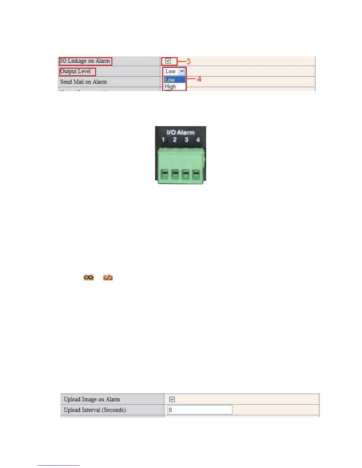
There are two options for Output Level. (Figure 10.2).
High: When chosen, the IO Pins work as a switch that is closed.
Low: When chosen, the IO Pins work as a switch that is switching off.
Figure 10.2
3.18.4 IO Pins for IO Alarm Linkage
Figure 10.3
I/O PINS: 1 Output 2 Output 3 Alarm input 4 Input (GND)
Input pins: The input pins can be used for 1-way external sensor input. For example, you may connect a
Passive Infrared Sensor (PIP) to it for motion detection. When external sensor triggered, IP CAMERA can be
programmed to send an e-mail with picture or control the internal relay output.
If you link an external alarm device to Pins 3 and 4, when Alarm Input Armed is selected (Figure 10.0),
external alarm is enabled.
Output pins: The output pins can be enable IO linkage on alarm.
You can also use
& to control IO output Switch ON/OFF (See Figure 4.4).
NOTE: All the pins work as switch only.
3.19 Send e-mail on Alarm
When chosen, it will send picture and e-mail to your e-mail once alarmed. (First you should finish the e-mail
Service Settings. Figure 9.1).
NOTE: It usually will send 6 snapshots by one e-mail to your mailbox for each alarm triggered. Each alarm will
last for 60 seconds.
Upload Image on Alarm
Enable Upload Image on Alarm to set upload images to FTP once alarmed.
Upload Interval: Set the upload interval (Seconds).
NOTE: The total alarm time is 60 seconds.
Figure 10.4