FCA‐22InstructionManual
Page7
InstallationandStartUp
GeneralInformation
Mount the FCA‐22 in a location where there is easy access to the analyzer and sensors.Install the
systeminanareawherevibrations,electromagneticandradiofrequencyinterferenceareminimizedor
absent.
Do not mount in direct sunlight or areas of extreme heat. The FCA‐22 is suitable for outdoor use if
mounte
dwithaprotectivecoverorsunshield.
SampleRequirements
The constant head flow controller can adapt to changing sample flows between 10 and 80 gal/hr
(40‐300L/hr).
Minimumflow:10gal/hr(38L/hr)
SamplePressure:1to30psig(0.1‐2bar)
Temperature:32°to122°F(0°to50°C)
MountingandConnec
tingtheInletandDrainfitting s
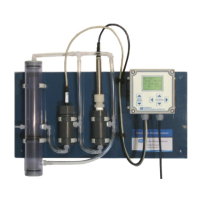
The FCA‐22 is intended for wall mounting only. The sensors insert into the flow cells as shown in the
figures. A ¼” barbed fitting is provided for the sample inlet. If desired, a ¼”compressionfitting can be
used.Th
esample inlet is ¼” FNPT.The sample drains through the¾” FNPT holeatthe bottom ofthe
CHFD.Attacha¾”fittingtoalengthofsofttubingandallowthewastetodraintoopenatmosphere.Do
not restrict the drain line.The sample can be introduce
d after the sensors have been calibrated and
installedintheflowcells.
PoweringtheC‐22
Attach power as described in the C‐22 manual.Tighten the cable glands provide a good seal to the
cable.
InstallingtheSensors
The FCA‐22 is supplied with the sensor cables pre‐wired to the analyzer. Th
e FCA‐22 instrument and
sensorswerecalibratedatthefactoryandshouldbereadyforusewhenassembled.However,changes
mayhaveoccurredduringshippingandstoragerequiringrecalibration.(SeeCalibrationsectionbelow)
The pH sensor mounts in the Flow Cell using the supplie
d ¾” compression gland fitting. Remove the
protectivecapandsaveitforfutureuse,thecapcontainsapotassiumchloridesolutionusecarewhen
removingthecapfromthesensor.Loosenthecompressionfittingtoallowthesensortospinfreelyin
thefitting.Insertthesensorintotheflowcellan
dhandtightentheglandfitting.RetractthepHsensor
approximately ½” from the bottom of the flow cell and hand tighten the compression nut to fix its
position.TheChlorinesensorisheldintheflowcellwithaunionnut.Removetheprotectivecapand
saveitforfutureuse.Slideth
esensorintotheflowcellandhandtightentheknurlednut.