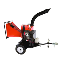
8 6 INCH CHIPPER
ASSEMBLY
Keep nuts as tight as possible while allowing the
discharge tube to freely turn.
NOTE
5. Lubricate the tube by applying grease to the grease
zerk at the base of the tube. Rotate the tube and
apply grease until the tube rotates freely.
6. Rotate the tube 360 degrees and lock it in place with
the lock pin to make sure it is mounted correctly.
7. Attach the discharge deector (7) to the discharge
tube. Connect the deector with two 5/16 x 1-1/4"
bolts (8) through the lower hole in the discharge tube.
Run these bolts through the inside of the tube, 3/8"
washer (12), deector, 5/16" washer (13), and then
knob (9).
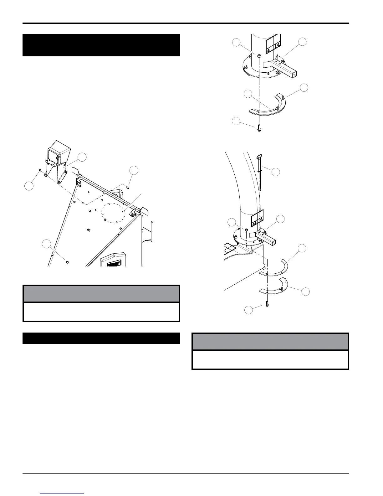
1. Attach one clamping ring (1) and one spacer ring (2)
to discharge tube base (3) using three 3/8 x 1-1/4"
bolts (4) and nylock nuts (5). Tighten leaving 1/16"
gap to assist in mounting to ange. See Figure 2.6.
2. Slide the tube onto the mounting ange on the
chipper frame. The discharge clamp (1) should slide
underneath the lip of the ange. Tighten the bolts to
secure it.
3. Install the second half of the spacer (2) and clamp
ring (1) on the discharge tube with 3/8 x 1-1/4" bolts
(4) and nylock nuts (5).
4. Attach lanyard with discharge pin (6) as shown in
Figure 2.8. Loop on lanyard installed below nut
located under discharge handle.
Figure 2.6, Attach Clamp Ring and Spacer
2
3
4
5
1
Figure 2.7, Attach Discharge Tube
2
1
3
4
5
6
1. Remove the bolts (1) and nuts (2) attaching the digital
display controller mount assembly (3) to the inside of
the chute.
2. Attach mount assembly to the outside of the chute as
shown.
3. Route harness using the zip ties and two holders (4)
shown in Figure 2.5. Leave excess harness at the
controller to allow rotation of the enclosure from side
to side
The controller mount assembly can be attached to the
chute in either set of mounting holes.
NOTE
Figure 2.5, Digital Display Controller Enclosure
ADDITIONAL
MOUNTING
HOLES
1
2
3
4
2.6 ATTACH DIGITAL DISPLAY
CONTROLLER MOUNT ASSEMBLY
2.7 ATTACH DISCHARGE TUBE