236 INCH CHIPPER
ENGLISH
SERVICE & MAINTENANCE
WARNING
BEFORE INSPECTING OR SERVICING ANY PART OF THIS MACHINE, SHUT OFF POWER SOURCE, DISENGAGE THE
HYDRAULICS, OPEN SHIELD AND MAKE SURE ALL MOVING PARTS HAVE COME TO A COMPLETE STOP.
5.12 ROTOR BEARINGS
6. Reinstall the belt idler pulley into the idler arm
weldment using the 1/2" hardware. Make sure the
belt pin (5) is positioned so that it does not contact
the bolt while engaged and tighten securely.
7. Check pulley alignment by placing a straight edge
across the face of both pulleys. Adjust the lower (engine)
pulley if necessary to bring them into alignment.
8. Check belt tension and adjust if needed. For proper
belt tension, tighten the adjustment bolt on the tension
spring(s) of the idler pulley until there is 1/8-3/16" gap
between the coils when the idler is engaged.
9. Reinstall belt guard.
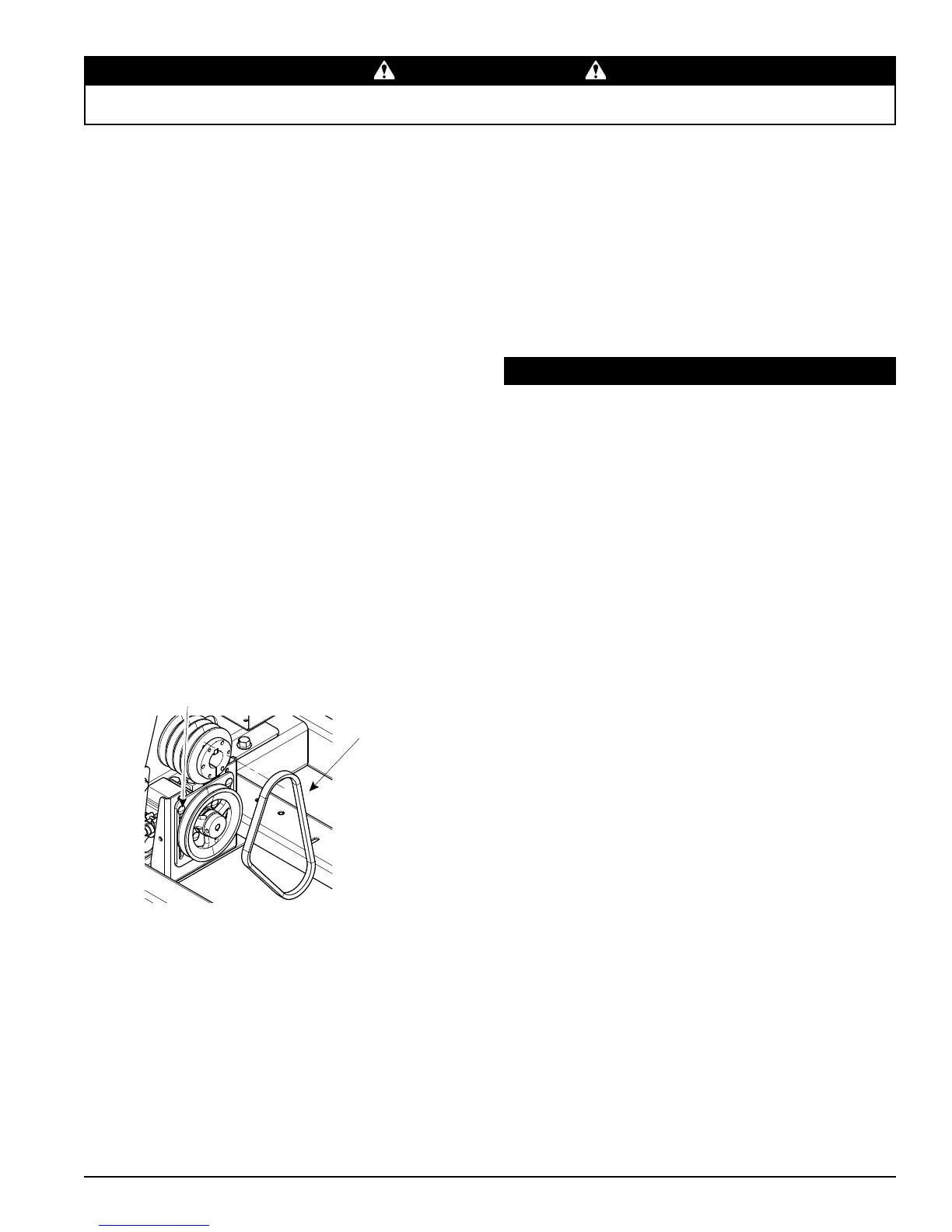
5.11.2 REPLACING HYDRAULIC DRIVE BELT
Check the condition of the hydraulic drive belt annually or
after every 50 hours of operation, whichever comes rst.
If the belt is cracked, worn, frayed, or stretched, replace it.
To replace the belt:
1. Remove the drive belt as explained in the previous
section.
2. Loosen the two bolts below the pulley as shown in
Figure 5.8 and push the pulley slightly upward to
loosen the tension on the hydraulic belt.
3. Remove the hydraulic belt from the pulleys and
discard.
4. Install new hydraulic belt on pulleys.
5. Push the pulley downwards and tighten the bolts to
tension the belt.
6. Install drive belt on pulleys.
7. Lower belt idler.
8. Reinstall the belt idler pulley into the idler arm
weldment using the 1/2" hardware. Tighten bolt to
proper torque.
LOOSEN
BOLTS
HYDRAULIC
BELT
Figure 5.8, Replacing Hydraulic Belt
1. Remove the two 3/8" retaining bolts holding the
access cover to the main frame assembly.
2. Open access cover to allow access to rotor.
3. Follow Section 5.11.1 to remove drive belt.
4. Remove the bolts attaching the pulley bushing to the
pulley.
5. Install the bushing push bolts and tighten alternately
one at at a time to remove the bushing from the
pulley.
6. Remove the pulley and the pulley bushing.
7. Remove bearing cap and bearing lock.
8. Loosen both bearing set screws on each bearing.
9. Remove four bearing mounting bolts on each bearing.
10. Lift rotor out of chipper housing.
11. Remove bearings and install new bearings with
grease zerks. Reinstall shims.
12. Install the eight bearing mounting bolts with washers
through the bearing and chipper housing. Torque to
75 ft-lbs.
13. Verify that there is no shaft end play.
14. Install the bearing locks.
15. Tighten bearing set screws.
16. Verify blade to anvil clearance is 1/16 to 1/8" on all
blades.
17. Place pulley bushing on shaft.
18. Place pulley on bushing.
19. Align pulley with engine pulley using a straight edge.
20. Alternately tighten bushing bolts one at at a time.
21. Follow instructions in Section 5.11.1 to reinstall belt.
22. Close access cover.
23. Replace the two 3/8" retaining bolts holding the
access cover to the main frame assembly and tighten.
9. Check pulley alignment by placing a straight edge
across the face of both pulleys. Adjust the lower
(engine) pulley if necessary to bring them into
alignment.
10. Check belt tension and adjust if needed. For proper
belt tension, tighten the adjustment bolt on the tension
spring(s) of the idler pulley until there is 1/8" – 3/16"
gap between the coils when the idler is engaged.
11. Reinstall belt guard.