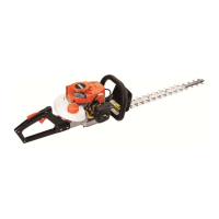
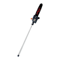
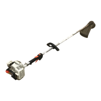
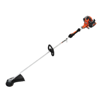
DSRM-200 DESCRIPTION
X7508161200 13
© 3/2014 ECHO Inc.
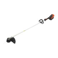
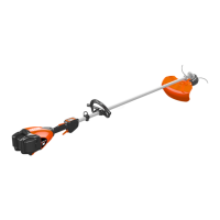
1. GEAR CASE
2. DRIVE SHAFT ASSEMBLY – Includes the drive shaft, throttle handle, support handle, and safety
decals.
3. SUPPORT HANDLE - FOR LEFT HAND - Grip for Left Hand.
4. STOP SWITCH - “SLIDE SWITCH” mounted on top of the throttle handle. Move switch FORWARD to
RUN, BACK to STOP.
5. THROTTLE TRIGGER LOCKOUT - Operation of the throttle trigger is prevented unless throttle trigger
lockout lever is engaged.
6. SPEED SELECTOR SWITCH - Select the speed position or the speed position.
7. THROTTLE TRIGGER - Spring loaded to return to idle when released. During acceleration, depress
gradually for best operating technique.
8. THROTTLE HANDLE - FOR RIGHT HAND - Contains Stop Switch, Throttle Lockout, and Throttle
Trigger.
9. POWER HEAD – Houses Motor and Battery.
10. PLASTIC DEBRIS SHIELD ASSEMBLY - MUST be installed on unit. Shield assembly includes the
Cut-Off Knife. Mounts on the Gear Housing Assembly just above the cutting attachment. Helps protect
the operator by deflecting debris produced during the trimming operation.
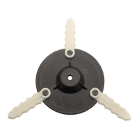
11. CUT-OFF KNIFE - Automatically trims line to the correct length after head is tapped on the ground. If
trimmer is operated without a cut-off knife, the line will become too long and motor damage may occur.
12. NYLON LINE HEAD - Contains replaceable nylon trimming line that advances when the trimmer head is
tapped against the ground while the head is turning at normal operating speed.