Do you have a question about the Echo GT-1100 and is the answer not in the manual?
Warns against using steel blades and requires approved attachments and correct shield.
Provides guidelines for safe fuel storage, refueling, and handling to prevent fires.
Details required safety gear like eye protection, gloves, and proper fitting clothing.
Advises against operating while fatigued or under the influence of drugs or alcohol.
Details the correct fuel-to-oil ratios (32:1 and 50:1) and mixing procedure.
Provides notes on safe starting practices like clearing the area and proper rope pulling.
Step-by-step guide for starting a cold engine, including choke and throttle use.
Procedure for starting the engine when it is already warm.
Instructions on how to properly stop the engine and troubleshooting the stop switch.
Tips for safe operation, preventing clogs, and avoiding damage from heat or obstructions.
Explains how to adjust the carburetor for proper idle speed control.
Step-by-step guide for adjusting the idle speed screw on the carburetor.
Detailed steps for replacing nylon line on the Echomatic trimmer head.
This document serves as the Operator's Manual for ECHO Weed & Grass Trimmers, specifically models GT-1100 and GT-2101. These units are described as lightweight, high-performance, gasoline-powered tools designed for trimming weeds and grass in areas that are difficult to manage by other means. The manual provides comprehensive information necessary for the assembly, operation, and maintenance of these trimmers.
The manual begins with crucial safety warnings, emphasizing the importance of understanding and following all instructions. It uses "DANGER" symbols to highlight procedures that, if not followed, could lead to serious, immediate, and irreversible human injury or death. "CAUTION" symbols are used for procedures that could result in serious, though not necessarily immediate, human injury or death. Users are instructed to follow all danger and caution warnings in the manual and on the safety decals affixed to the trimmer. These decals are for the user's protection, and it's essential to ensure they remain legible and their instructions are understood.
A critical safety warning states, "Do not use steel blades on this unit." These trimmers are not designed for steel blades, and their use may cause serious injury. Users must always obey local ordinances regarding internal combustion engines and only use cutting attachments approved and supplied by ECHO INC. Operating the unit without the shield in the correct position is strictly prohibited.
Safe fuel handling practices are detailed, including storing gasoline in an approved container, never smoking while handling gasoline, and always stopping the engine before refueling. It's advised not to refuel a hot engine and to wait until it cools. The fuel cap should be removed slowly to relieve pressure, and overfilling the tank or spilling fuel should be avoided. The engine must be restarted at least 10 feet away from the refueling point.
The manual warns against operating the trimmer in confined areas due to the risk of carbon monoxide poisoning. It also stresses the importance of keeping people and animals away from the work area during operation. Before starting, the work area must be inspected, and all stones, cans, bottles, wire, and other foreign objects should be removed.
Operators are required to wear safety protection that meets A.N.S.I. Z87 standards, including gloves and non-skid footwear. Proper attire includes snug-fitting, durable clothing, and loose clothing should be avoided.
Operating the unit while fatigued or under the influence of drugs or alcohol is prohibited. Operators must remain alert to prevent injury to themselves and others. The correct technique involves holding the unit firmly with both hands, with fingers and thumbs encircling the handles.
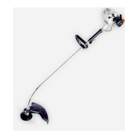
The manual provides a visual breakdown of the trimmer's components, including the spark plug, muffler, cylinder, air filter, fuel tank cap, fuel tank, recoil starter handle, drive shaft assembly, loop handle, cutter head, shield, ignition switch (for both GT-1100 and GT-2101 models), throttle trigger, and engine.
The trimmers use 2-cycle fuel. For 32:1 ECHO Oil, a mixture of 32 parts leaded or unleaded regular grade gasoline (minimum 87 Octane) and one part 32:1 ECHO 2-stroke oil is required. For 50:1 ECHO Approved Oil, a mixture of 50 parts leaded or unleaded regular grade gasoline (minimum 87 Octane) and one part 50:1 ECHO 2-stroke oil is specified. A crucial note for both is: "Do not use gasohol or alcohol blended fuels in this engine."
Fuel should never be mixed in the engine's fuel tank. The recommended procedure is to pour half the gasoline into a safe container, add the oil, mix, then add the remaining gasoline and remix. After mixing, the fuel tank cap should be installed, and any spilled fuel wiped clean.
Before each use, operators must check for loose nuts, bolts, and screws.
Safe starting techniques include clearing the work area of debris, holding the unit firmly, using short pulls (1/2 to 2/3 of rope length) when pulling the starting rope, and not allowing the starter handle to snap back against the housing.
A "DANGER" warning indicates that the cutter head may rotate even in a low-speed position when the engine starts. To start a cold engine:
Operators must keep both hands on the handles when the engine is running. If the cutter becomes clogged, the engine must be stopped, and the cutter cleaned. Overreaching or standing on unstable surfaces is prohibited. If the trimmer is operated for extended periods in high temperatures, the driveshaft housing may become very hot. In such cases, the unit should be allowed to cool, and lubrication checked as outlined in the service section. To prevent engine damage, the unit should not be run at full throttle without a load. If the cutter head strikes an obstruction or is prevented from turning freely, the engine must be stopped, and the cutter head inspected for damage.
The recommended line length is 5 inches, measured from the edge of the cutting head to the tip of the line. Trimming is done with the tip of the line; cutting with the entire length can cause the line to snap or fray. If the line is too long, the cut-off knife will automatically trim it to the correct length during operation.
With the engine running at normal operating speed, the head should be tapped firmly on the ground. One inch of line will be released each time the head is tapped.
With the engine stopped, line should be unwound from the spool until the proper length is achieved.
The trimmer should be placed so the cutter faces straight ahead. A "CAUTION" warns that tilting the head to the right will throw debris towards the operator. To trim, the unit should be tilted slightly to the left, allowing debris to be thrown away from the operator.
Scalping involves removing all vegetation down to the ground. The cutter head should be tilted about 30 degrees to the left. This technique is effective around trees and shrubs, but care must be taken not to bruise bark or young sensitive growth. When trimming around flowers, the line cuts in a full circle around the head.
The cutter head should be tilted at right angles to the ground. The handle bracket should be adjusted to fit the edging position. The line should skim along the edge of concrete or other hard surfaces. A "CAUTION" explicitly states: "Never use ECHO units with blades for edging."
For sweeping, the cutter head should be tilted slightly to the left and swung side to side.
A "DANGER" warning for mowing states that debris may be thrown in any direction, and eye protection must always be worn.
The manual includes a detailed troubleshooting section covering common issues like engine failure to start, difficulty starting, engine misses, lack of power, overheating, noisy/knocking engine, and stalling under load. For each problem, potential causes are listed, along with corresponding "WHAT TO DO" solutions, ranging from simple checks (e.g., fill tank, clean strainer) to more complex adjustments (e.g., carburetor adjustment) or recommendations to contact an authorized dealer.
The idle speed adjustment screw controls the throttle opening at idle. If the idling adjustment is too low or too high, the following procedure should be used:
Note: Use 3.65 m (12 ft.) of line.
Note: The engine is delivered separated from the shaft, with the throttle cable attached to the shaft.
The manual concludes with information on how to obtain replacement Parts Books, requiring completion of an order form and enclosing a check or money order for $2.00, payable to ECHO, INCORPORATED. It provides the mailing address and specifies the Parts Book numbers for models GT-1100 (898-696-44330) and GT-2101 (898-696-44430).
| type of engine | Air-cooled, two-stroke, single-cylinder, gasoline engine |
|---|---|
| bore | 32.2 mm |
| stroke | 26.0 mm |
| displacement | 21.2 cc |
| fuel | Mixed fuel |
|---|---|
| fuel oil ratio | 32:1 ratio with ECHO oil or 50:1 ratio with ECHO oil |
| fuel tank capacity | 0.4 lit. |
| ignition system | Flywheel magneto, capacitor discharge ignition type |
|---|---|
| spark plug | NGK BPM7A, CHAMPION CJ-7Y |
| starter system | Automatic rewind system |
| length | 1.4 m |
|---|---|
| width | 330 mm |
| height | 360 mm |
| weight | 8.4 lbs |
| type of engine | Air-cooled, two-stroke, single-cylinder, gasoline engine |
|---|---|
| bore | 32.2 mm |
| stroke | 26.0 mm |
| displacement | 21.2 cc |
| fuel | Mixed fuel |
|---|---|
| fuel oil ratio | 32:1 ratio with ECHO oil or 50:1 ratio with ECHO oil |
| fuel tank capacity | 0.4 lit. |
| ignition system | Flywheel magneto, capacitor discharge ignition type |
|---|---|
| spark plug | NGK BPM7A, CHAMPION CJ-7Y |
| starter system | Automatic rewind system |
| length | 1.4 m |
|---|---|
| width | 330 mm |
| height | 360 mm |
| weight | 8.8 lbs |