10
Before you start
Assembly
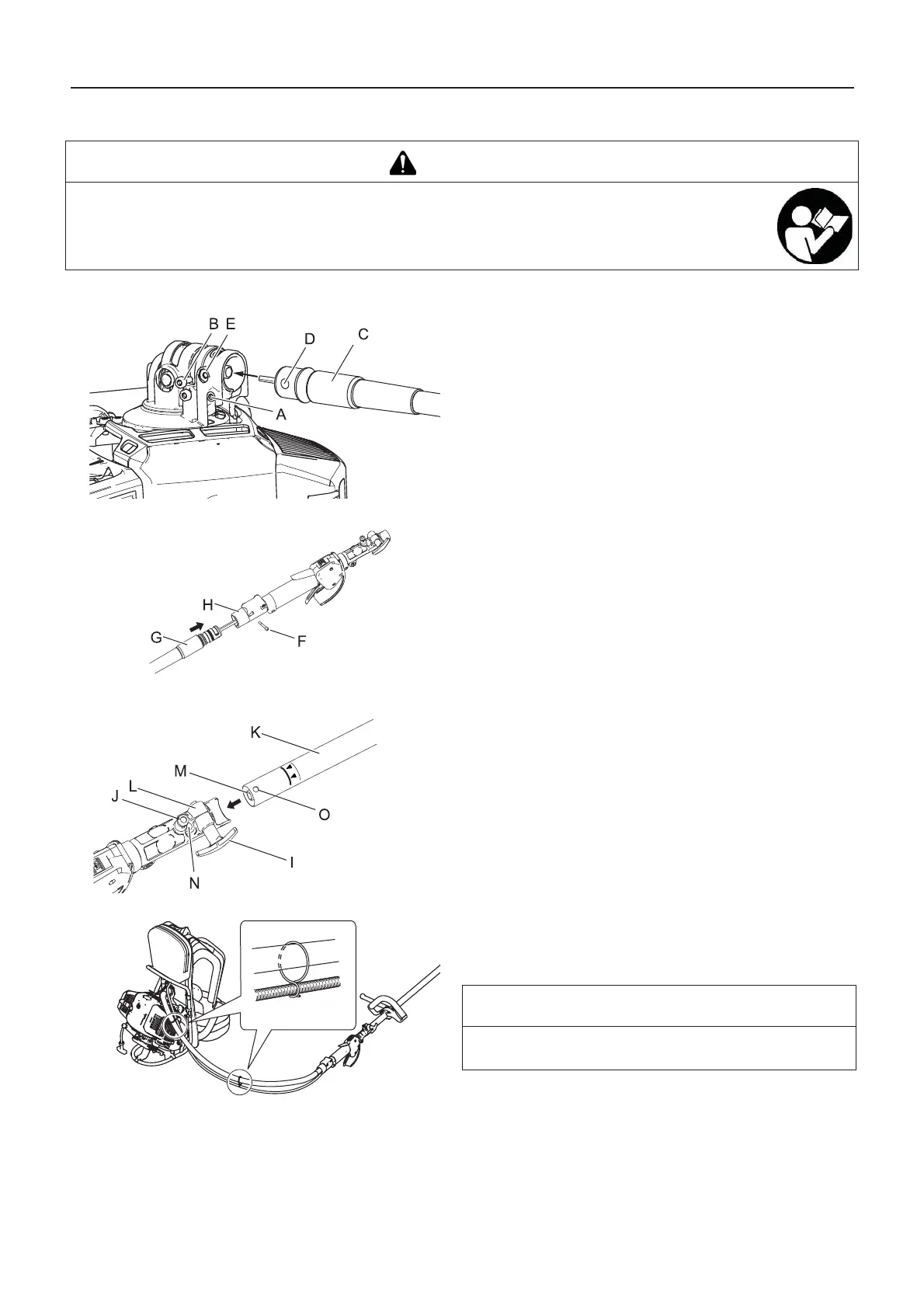
Operation shaft assembly
1. Loosen the bolt (A).
2. Remove the lock bolt (B).
3. Insert the flexible shaft assembly (C) into the angle transmis-
sion.
4. Align the hole of the flexible shaft assembly (D) with the hole
of the angle transmission (E).
5. Tighten the lock bolt and bolt.
6. Remove the lock bolt (F).
7. Insert the flexible shaft assembly (G) into the trigger tube.
8. Tighten the lock bolt.
9. Loosen the clamping knob (I).
10. Pull locator pin (J) out, and turn anticlockwise 1/4 turn to
lockout position.
11. Insert the operation shaft assembly (K) into the coupler (L)
as aligning the socket (M) with the flexible shaft (N).
12. Rotate locator pin 1/4 turn clockwise to engage operation
shaft hole. Insure locator pin is fully engaged by twisting op-
eration shaft. Locator pin should snap flush in coupler. Full
engagement will prevent further shaft rotation.
13. Tighten the lock bolt.
14. The two pieces of clip attached to flexible shaft assembly
must be set to appropriate positions on the throttle cable (at
equal distance on the whole length of the flexible shaft as-
sembly).
WARNING
Read the operator's manual carefully to ensure that you assemble the product correctly.
Using a product that has been incorrectly assembled could lead to an accident or serious injury.
NOTE
To disassemble, reverse assembly instructions. Insert the
plastic cap to the coupler in order to prevent grease leakage