Betriebsanleitung · User Guide
8
[ 3. Vor dem Einbau ]
●
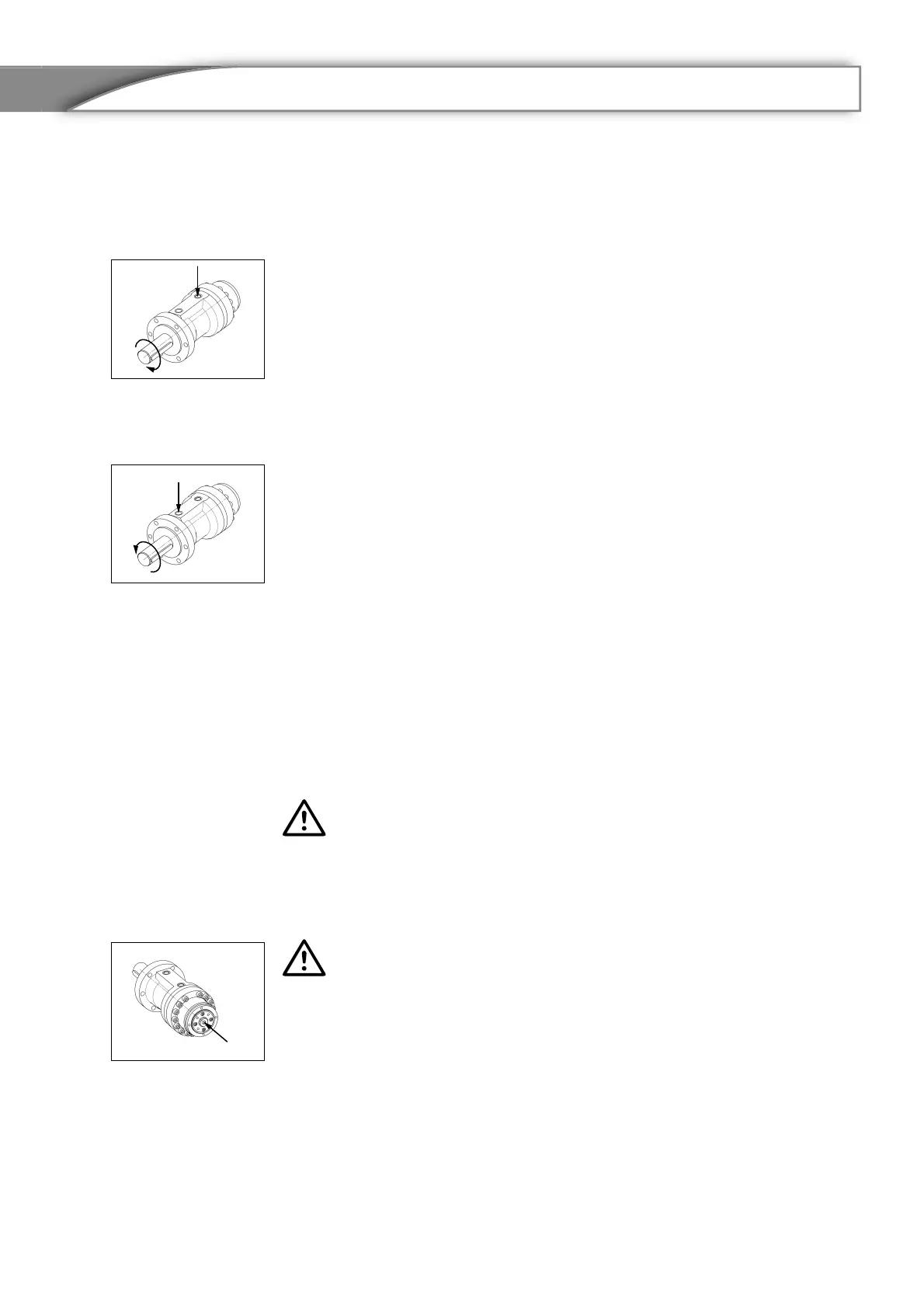
Bei Druckbeaufschlagung in
Anschluss B1 dreht sich die
Abtriebswelle in Richtung B
(Uhrzeigersinn) und der Kolben
K bewegt sich in Richtung E1 bis
zur internen mechanischen End-
lage. Diese Endlage ist die
Grundstellung und nicht verstell-
bar.
●
Bei Druckbeaufschlagung in
Anschluss A1 dreht sich die
Abtriebswelle in Richtung A
(gegen Uhrzeigersinn) und der
Kolben K bewegt sich in
Richtung E2 bis zur internen
mechanischen Endlage. Diese
Endlage ist verstellbar (siehe
Kapitel 11).
[ 4. Einbau ]
●
Farbe oder sonstige anhaften-
den Fremdteile müssen von der
Flanschauflage entfernt werden.
●
Es ist darauf zu achten, dass die
Abtriebswelle W mit der Nabe,
sowie die Flanschflächen genau
fluchten, da sonst die maximal
zulässigen Radial- und Axialkräf-
te überschritten werden können.
●
Zur Montage der Abtriebswelle
W mit der Nabe ist die erfor-
derliche Axialkraft durch Schub
über das Wellenende der
durchgehenden Abtriebswelle
W oder durch Zug mittels Ge-
windestange am Gewinde GW
vorzunehmen. Eine andere Mon-
tageweise kann bei Schwer-
gängigkeit zur Überschreitung
der Axialkraft und damit zum
Lagerschaden führen.
[ 3. Before installation ]
●
When pressure is applied in port
B1 the drive shaft turns in direc-
tion B (clockwise) and the piston
K moves in direction E1 up to the
internal mechanical end position.
This end position is the positve
stop and is not adjustable.
●
When pressure is applied in port
A1 the drive shaft turns in direc-
tion A (anti-clockwise) and the
piston K turns in the direction E2
to the internal mechanical end
position. This end position is
adjustable (see section 11).
[ 4. Installation ]
●
Paint or other parts stuck to the
flange must be removed.
●
Care should be taken to align
the drive shaft W perfectly with
the hub and the flange surfaces,
to avoid exceeding the maxi-
mum permitted radial and axial
forces.
●
The required axial force for mo-
unting the drive shaft on the hub
can be generated by pushing on
the end of the continuous drive
shaft W or by pulling using the
threaded rod on the thread GW.
Mounting using a different me-
thod can mean exceeding the
axial force if there is tightness
and this can lead to bearing da-
mage.
B1
A1
B
A