48
Accelerating the path to discovery
®
6. Control Key (*)–When pressed, the display shows the set point temperature. To decrease or increase the
set point, press the
key (4) or
key (5), while simultaneously depressing the control key (*). The display’s
representation of the set point is a ashing number.
7. System Lights–They are used to indicate the ON/OFF status of the heating mantle elements connected through
the power receptacle (13).
8. System Switches–They are used to turn the elements of the heating mantle ON or OFF by regulating the power
which ows to the power receptacle (13).
9. Reset Button–On start-up, after a power failure, and when there’s an over-temperature the reset button is used
to reset and restart the controller.
10. Reset Light–The reset light illuminates after a power failure, when there’s an over-temperature, and upon start-
up to indicate that the reset button must be pushed for power to ow through the system.
11. Main Switch–This provides electricity to the digital controller when toggled ON and cuts o the electricity supply
when toggled OFF.
12. Temperature Sensor Input–This is a receptacle through which the temperature sensor, or thermocouple, in this
case, is connected to the controller. Ecodyst recommends that you utilize the thermocouple provided with your
entire unit purchase or use a similar one of the same type for the acute eciency of communication within the
system. The correct thermocouple type has the same color plug as the temperature sensor receptacle.
13. Power Receptacle–The heating mantle can be connected to the controller via the power receptacles, located on
the rear panel of the controller box.
14. Power Chord–Serves as a channel through which electricity is supplied to the controller.
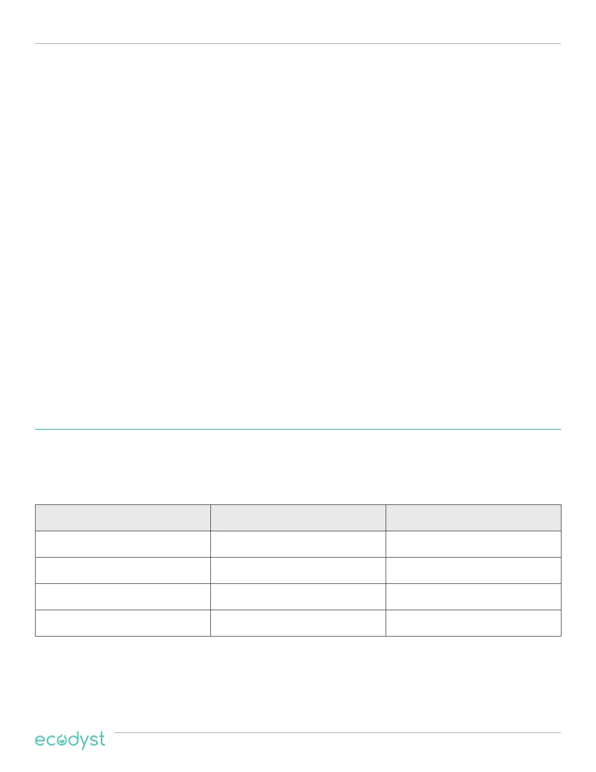
The table below shows each controller along with its corresponding current and voltage.
WARNING: Use only resistive loads that may be operated safely at the given voltage and a current lower than
the listed current. If not, the controller could be damaged, creating a safety issue.
3.2 Heating Mantle Restrictions
NOTE: Do not connect your controller to low voltage oil baths. If not connected to the controller properly, many
oil baths, which are neither 120 nor 240VAC equipment, might cause res.
Model Number Output Voltage Maximum Output Current
HPC15-Pro 208-240VAC, 1-ph, 50–60Hz 15 Amps
HPC30-Pro 208-240VAC, 1-ph, 50–60Hz 30 Amps
HPC50-Pro 208-240VAC, 1-ph, 50–60Hz 50 Amps
HPC50-3PH-Pro 208-240VAC, 3-ph, 50–60Hz 80 Amps
High Powered Heating Mantle Controllers
 Loading...