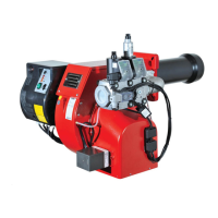
LB 429 Blu 170 ÷ 350 P /P AB B
pag.17
To calculate the burner’s working output, in kW, proceed as follows:
- Check at the meter the quantity of supplied litres and the duration, in seconds, of the
reading, then calculate the burner’s output through the following formula:
CALCULATION OF WORKING OUTPUT OF THE BURNER
e
x f = kW
s
e = Litres of gas
s = Time in seconds
G20 = 34,02
G25 = 29,25
G30 = 116
G31 = 88
f
COMBUSTION ADJUSTMENT
WARNING: In order to have a correct combustion and thermal output adjustments, these must be carried out together with a
combustion analysis, to be executed through suitable devices, taking care that the values are the correct ones and are in accordance
with the local safety regulations. The adjustments must be carried out by qualified and skilled technicians authorised by Ecoflam
S.p.A.
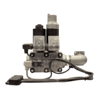
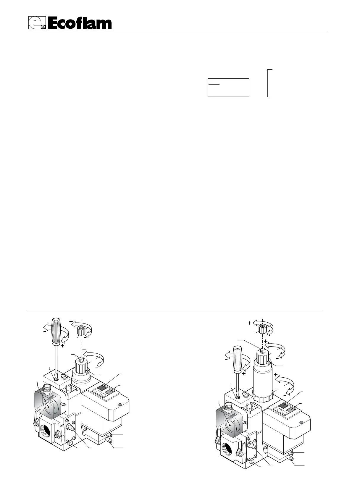
ADJUSTMENT OF PRESSURE GOVERNOR
The adjustment procedure is the same for both single-stage (MB-DLE) and two-stage (MD-ZRDLE) versions. Check that gas pipe
pressure is not higher than the maximum one specified for the governor, then operate through a screw driver fitted into the suitable
seat as shown in the figure. Adjustments must be made with the burner running, in function of the working pressure and needs of
each installation. The working fields are as follows: inlet pressure range 0÷100 mbar; outlet pressure range 3,6÷20 mbar. Between
the minimum and maximum outlet pressure there are approx. 60 adjusting screw’s turns. The governor is adjusted to an interme-
diate position during the tests.
ADJUSTMENT OF GAS FLOW RATE FOR SINGLE-STAGE VERSION (MB-DLE)
To adjust the gas flow rate, loosen screw R and turn the regulator; to the right (screwing) to reduce; to the left (unscrewing) to
increase. At the end tighten screw R.
ADJUSTMENT OF GAS FLOW RATE FOR TWO-STAGE VERSION (MB-ZRDLE)
Low flame: Loosen screw R and turn regulator P. To the right (screwing) to reduce flow rate; to the left (unscrewing) to increase. At
the end tighten screw R.
High flame: loosen screw R and turn regulator P. To the right (screwing) to reduce flow rate; to the left (unscrewing) to increase. At
the end tighten screw R.
ADJUSTMENT OF FAST OPENING’S HYDRAULIC BRAKE
The adjustment procedure is the same for both single-stage (MB-DLE) and two-stage (MD-ZRDLE) versions.
To adjust the fast opening’s hydraulic brake, unscrew cover T and through its upper side turn pin Q. Screw to reduce the opening
speed; unscrew to increase. Screw cover T after regulation.
ADJUSTMENT OF GAS SOLENOID VALVES
The ignition flow rate is carefully adjusted. during test phase to 1/3 of the maximum flow rate (according to specifications).
O
perations for eventual further adjustment must be carried out by skilled personnel authorized by ECOFLAM