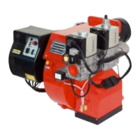
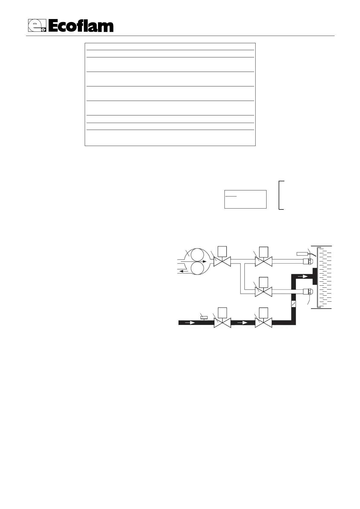
GAS CIRCUIT
SUCTION
RETURN
1 - PUMP
2 - SAFETY OIL VALVE
3 - LOW FLAME OIL VALVE
4 - HIGH FLAME OIL VALVE
5 - LOW FLAME NOZZLE
6 - HIGH FLAME NOZZLE
7-GAS PRESSURE SWITCH
8-SAFETY GAS VALVE
9-GAS VALVE
Error diagnosis
Error message Flash-Code Possible fault
lockout ❘ ❙ ❙ ❙ ❙ within lock out safety time
safety time no flame establishment
air proving switch ❘ ❙ ❘ ❘ ❘ air proving switch
in closed position contact welded
air proving switch ❘ ❘ ❘ ❙ ❙ air proving switch does not
time-out close within specified time
air proving switch ❘ ❘ ❘ ❘ ❙ air proving switch opens
opened during start or operation
loss of flame ❙ ❙ ❙ ❙ ❘ loss of flame during operation
Flash-Code for manual lock out
manual/external ❘ ❘ ❙ ❙ ❙ ❙ ❙ ❙ ❙ ❙
lock out
To calculate the burner’s working output, in kW, proceed as follows:
- Check at the meter the quantity of supplied litres and the duration,
in seconds, of the reading, then calculate the burner’s output through
the following formula:
CALCULATION OF WORKING OUTPUT OF THE BURNER
e
x f = kW
s
e = Litres of gas
s = Time in seconds
G20 = 34,02
G25 = 29,25
G30 = 116
G31 = 88
f