Part 8 - Installing gas piping
Installation
Refer to CAN/CGA B149.1 installation codes, and local codes for gas piping requirements and sizing. Pipe
size running to the appliance depends on:
Length of pipe;
Number of fittings;
Maximum input requirement of all gas appliances in the residence.
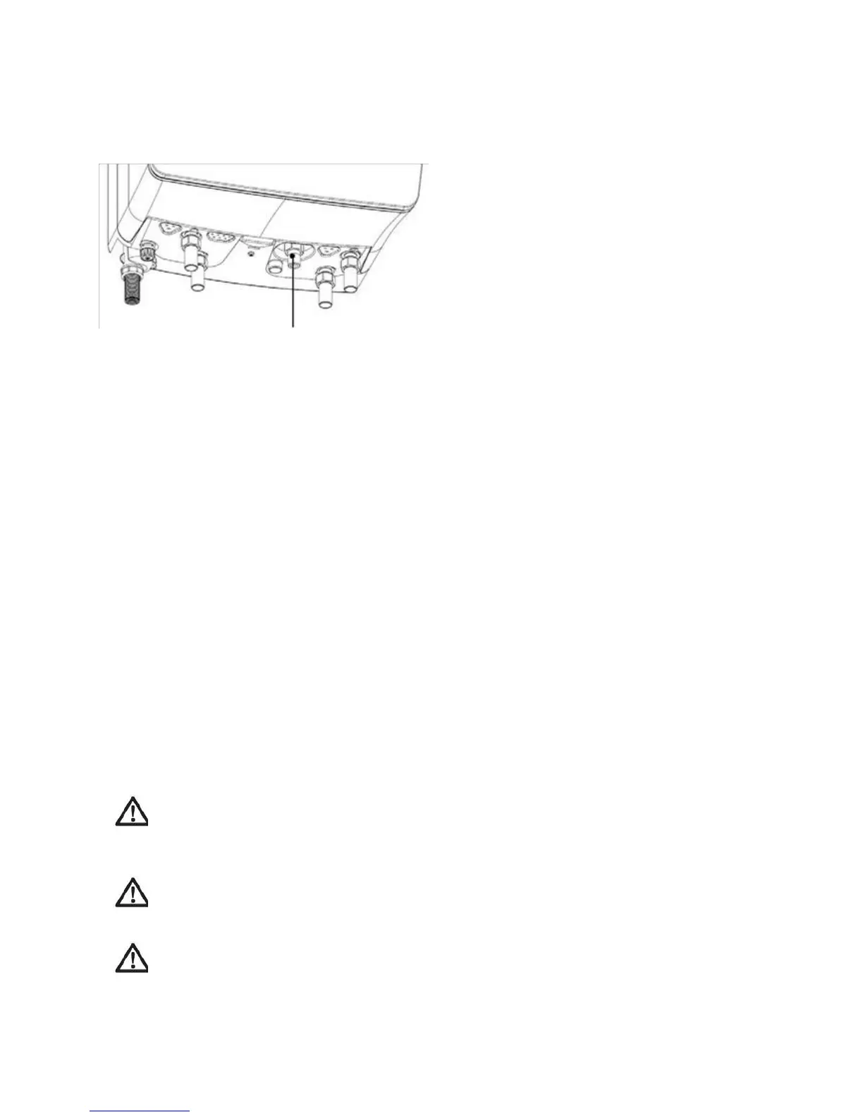
Figure 8.1 Gas line connection location
Connecting the gas line
The gas connection tube diameter is not indicative of the gas pipe that should be connected to it. For example
the connection on boiler is ½”, but the larger Eco King boilers at 187,000BTU require a larger gas pipe to be
piped to the boiler. Consult, for this purpose, the gas code to determine gas pipe size. It is necessary to install a
manual shutoff gas valve in front of the gas pressure regulator to make sure that the gas line can be closed in
case of maintenance. The entire piping system, gas meter and regulator must be sized properly to prevent
pressure drop greater than 1"wc as stated in the National Fuel Gas Code. If you experience a pressure drop
of greater then 1” the meter, regulator or gas line is undersized.
Ideally 7” to 10” wc of gas pressure when using Natural gas and 11 to 13” wc when using LPG, will be available
to the boiler gas valve inlet at maximum boiler operation. Minimum gas pressure required is 3.5”wc and
maximum is 14”wc during static and dynamic testing.
When an in-line regulator is used to drop gas pressure from 2psi to 0.5psi, it must be located a
minimum of 6ft from the Eco King Supreme.
Eco King recommends minimum ¾” diameter flex hose if flex gas hose is going to be used.
Ensure that:
The gas line connection to the appliance does not apply any weight to the gas valve.
Create an installation layout such that the piping does not interfere with the vent pipe, or any
other serviceable components.
The appliance shall be installed such that the gas ignition system components are protected
from water (dripping, spraying, rain etc.) during installation and servicing.
The gas piping is large enough for all the appliances in the home. No appreciable drop in line pressure
should occur when any unit (or combination of units) lights or runs. Use common gas line sizing
practices. Make sure the gas pressure is within specification during all conditions.
Always use a pipe-threading compound. Apply sparingly to all male threads, starting at two threads from
the end. Over doping or applying dope to the female end, can result in a blocked gas line.
DO NOT TIGHTEN FITTINGS WITHOUT SUPPORTING THE GAS VALVE
Install a manual “Equipment Shut-Off Valve”. Valve must be listed by a nationally recognized testing
lab. Should overheating occur or the gas supply fail to shut off, turn off the manual gas control valve.
The gas line piping can safely be removed from the appliance for servicing.
Leak test the gas pipe and clamp off the gas pipe up to the gas pressure regulator.
Carefully vent the gas pipe (outside in open air) before putting appliance into operation for the 1
st
time;
Warning
Strain on the gas valve and fittings may result in vibration, premature component failure and leakage and
may result in a fire, explosion, property damage, serious injury or death.
Warning
Do not use an open flame to test for gas leaks. Failure to follow these instructions may result in fire.
Warning
When performing a pressure test on the gas line piping, be sure the appliance is disconnected or isolated if
the test pressure is expected to exceed 3.5 kPa (0.5 PSI), as damage to the valve could occur resulting in fire,
property damage, serious injury or death.
47