Part 12 - Annual maintenance and inspection
Warning
Crystalline Silica - Read carefully the warnings and handling instructions pertaining to Refractory
Ceramic Fibers before commencing any service work in the combustion chamber. Take all necessary
precautions and use recommended personal protective equipment as required.
Make sure any gas is cleared from the combustion chamber. Turn the gas valve of.
Remove the burner:
1 Remove the four M6 nuts at the front plate of the combustion chamber.
2 Remove the ignition cable.
3 Disconnect the gas pipe of the gas valve.
4 Pull forward the burner unit including the fan.
Warning
Pull the burner forward halfway the furnace and remove the fan cable plug from the fan.
Never clean the burner yourself. If the inside of the heat exchanger / combustion chamber has been
contaminated and/or there is some deposit on the inside of the stainless steel tubes, remove the latter
with a vacuum with a high efficiency filter followed by cleaning with hard nylon brush or citric acid. Then
once again remove loose debris or dust with a vacuum cleaner. If necessary repeat this cleaning cycle
until the heat exchanger / combustion chamber is clean. If necessary use some plastic to protect
electrical components from being damaged by liquid dripping. Inspect the insulation disc located at the
back side of the combustion chamber. Replace if damaged. Do the same with the insulation disc
around the burner. Take into account handling instructions pertaining to Refractory Ceramic Fibers.
Warning
Do not use a wire brush for cleaning.
Check the inside of the heat exchanger.
Dismount the plastic air suction box on the suction side of the fan. Check the blades of the fan. If the
blades of the fan are covered with dirt, carefully clean every blade. If this is not done regularly, the
fan will not evenly rotate and get out of balance.
Check the distance between the electrode and the burner. This must run parallel with the burner at
a distance of approximately 5.5 mm (0.22 Inch).
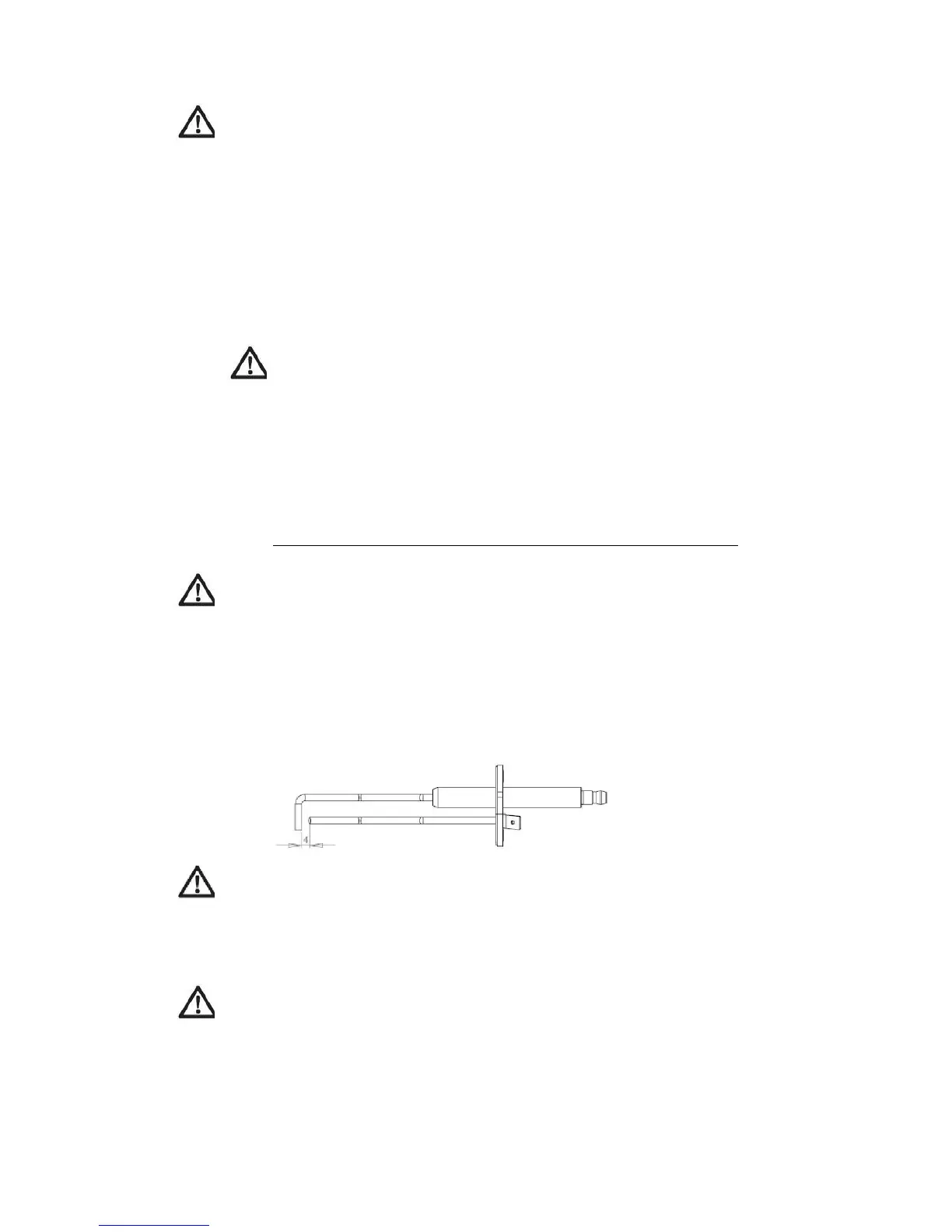
Use a ignition/ionisation pin to measure the flame impedance to the burner. See below.
Warning
The distance between the ignition pin and the earth pin must not exceed 4 mm (0.16”). If so, carefully
bend back the pin to a distance of 4 mm (0.16”).
Re-install the ignition pin, ignition cable, gas pipe and the burner door. Check for gas leaks.
Warning
Replace any gaskets or insulation discs that show any signs of damage and do not re-use.
Failure to follow these instructions may result in fire, property damage or death.
64