4.5.1 Connection of hose
Note data on the in-pack notelet with the hose connecting elements!
n Cut the hose (
Ä
Chapter 4.5 ‘Installation of hose or pipe’ on page 11, pos. 1) at right
angles.
n Slip the union nut (pos. 2) and clamping element (Pos. 3) over the hose.
n Slip the hose onto the cone (pos. 4) up to the stop collar.
n Position the O-ring seal (pos. 5) into the groove provided on the connecting adapter
(pos. 6).
n Connect the hose and cone (pos. 4) and tighten the union nut (pos. 2).
4.5.2 Connection of pipe
n Cut the pipe (
Ä
Chapter 4.5 ‘Installation of hose or pipe’ on page 11, pos. 1a) at right
angles.
n Slip the union nut (pos. 2) over the pipe.
n Weld / adhesive bond the insert (pos. 3a) to the pipe.
n Position the O-ring seal (pos. 5) in the groove provided on the connecting adapter
(pos. 6).
n Tighten the union nut (pos. 2).
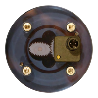
4.6 Electrical connection
The OGM
PLUS
electronic evaluation system is moulded into the cover
.
Electrical connection is accomplished by means of a four-pole M12 connector.
4.6.1 Connection to (SPS) control systems
The OGM
PLUS
is supplied with PNP output. However
, it can be
reprogrammed to NPN output if required.
If you use your own PLC cable instead of our prefabricated PLC cable, it is
imperative that a bridge is placed in the connector between PIN 3 and 2.
If this bridge is not present, malfunctions / failures may occur.
Installation
12417102601 Rev. 1-12.2019