
C
Claire BurnsAug 15, 2025
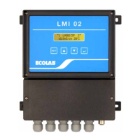
What to do if Ecolab LMI 02 Measuring Instruments show no metering despite concentration undercut?
- JJeffrey GibbsAug 15, 2025
If there is no metering despite concentration undercut, check the metering enable connection on the instrument and system. Also, verify that the rated value setting is correct, the product storage container is not empty, and the max. metering time has not expired.