417102012_LMI02.doc - 85 - Rev. 9-07.08
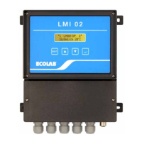
8 Checking the conductivity display
The conductivity display of the LMI02 can be checked with the conductivity simulator for
LMIT08 (item no. 289190) or with a calibration box for multronic (item no. 255195). It is
also possible to check this by dipping the conductivity probe into a sample solution of
known conductivity.
CAUTION
The conductivity probe should be brought to 20°C in order to check the conductivity
display and the current output.
When using a simulator, the ↵ key can be pressed to show the uncompensated
conductivity value (a * symbol appears in front of the conductivity display). The current
output is also adjusted to the uncompensated value.
Current output on LMI02
LMI02
measuring
range
With simulator for LMIT08
item no. 289190
Resistance value (label)
Conductivity
display
on LMI02
0..20 mA 4..20 mA
0... 20 mS/cm) 383 Ω (20.0 mS) 18.0 mS/cm) 18.0 mA 18.4 mA
0…200 mS/cm) 38.3 Ω (200 mS) 180 mS/cm) 18.0 mA 18.4 mA
Current output on LMI02
LMI02
measuring
range
With simulator for Multronic
item no. 255195
Resistance value (label)
Conductivity
display
on LMI02
0..20 mA 4..20 mA
0... 20 mS/cm) 345 Ω (20.0 mS) 20.0 mS/cm) 20.0 mA 20 mA
0…200 mS/cm) 34.5 Ω (200 mS) 200 mS/cm) 20.0 mA 20 mA
The adjustment of the conductivity display is described in chapter 7.3.2.1 of the LMI02
User’s Manual.
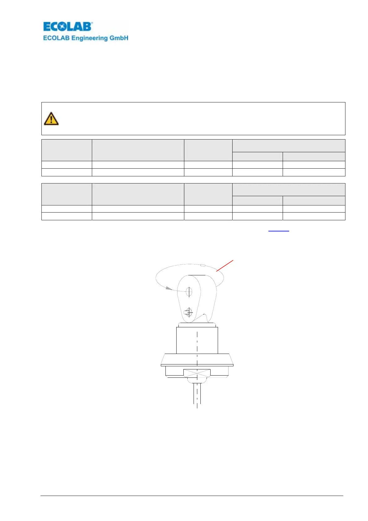
fig. 8.1
Loop resistance
(simulations resistance)
 Loading...