17
Step 4: Connect the Air Compressor Power Supply
The air compressor requires a dedicated power supply to prevent interaction with other equipment.
Provide a means of power disconnect adjacent to the air compressor in accordance with manufacturer’s
published instructions and in accordance with the applicable national and/or local codes (i.e., NFPA 70).
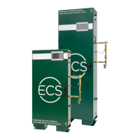
The incoming power supply line is connected to the terminal block inside the NEMA 4 power supply box
on the air compressor.
NOTE: Confirm the available power source is compatible with the wiring configuration of the air
compressor. Contact ECS if there is a discrepancy.
The auto-drain power supply: 120 VAC, 1 phase, 60 Hz unswitched power supply can be connected to
same power supply as the nitrogen generator.
Figure 2
NOTE: Ensure an appropriately rated disconnect switch and circuit breaker (minimum 15 Amps and a
Short Circuit Current Rating (SCCR) of 5 kVA) are installed in a suitable and accessible location in
accordance with the applicable national and/or local codes (i.e., NFPA 70).
Step 5: Plumb the Air Supply Line to Nitrogen Generator
Connect the air discharge plumbing from the air compressor to the air inlet of the nitrogen generator
using a minimum ½” black steel, galvanized steel, or copper lines. The air compressor start-up kit includes
a flex-hose connection to be installed between the air compressor and nitrogen generator to reduce
vibration.
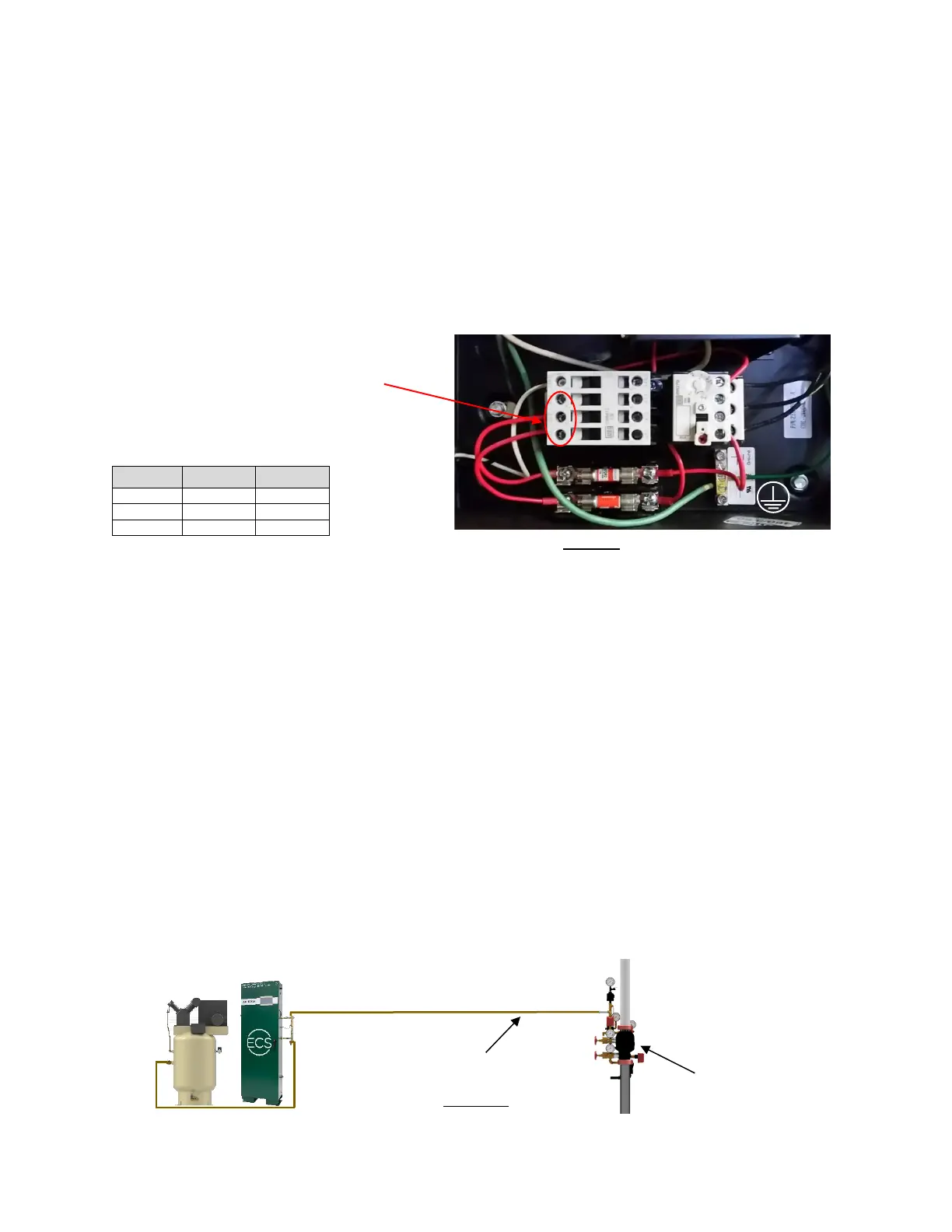
Step 6a: Plumb the Nitrogen/Air Supply Line - No Additional Air Compressor (Figure 3a)
The nitrogen/air discharge plumbing from the Nitrogen Generator must be connected directly to the dry
pipe or preaction valve trim using a minimum ½” black steel, galvanized steel, or copper lines. The size of
the nitrogen/air supply line must be based on both the length of pipe between the nitrogen generator
and fire sprinkler systems and the total volume of fire sprinkler systems being supplied.
NOTE: The Nitrogen Generator requires an in-line Air Maintenance Device (AMD) that is equipped with
an on-board field adjustable pressure regulator for each sprinkler system being served.
Acceptable AMD models are the Reliable Model A, Tyco Model AMD-1 and Victaulic Series 757.
Figure 3a
 Loading...