33
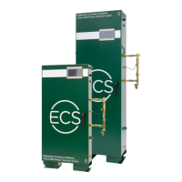
3. The second component of the SMART Vent is the electric control box. The control box must be
installed on a wall or vertical surface adjacent to the vent assembly installation location.
4. Provide conductors from 120 VAC, 60 Hz (200-240 VAC, 50 Hz) power supply to designated
terminals in the electric control box in accordance with the applicable national and/or local codes
(i.e., NFPA 70). The device draws less than 2 amps. Contractor must drill hole in the control box
to provide access for the 120 VAC, 60 Hz (200-240 VAC, 50 Hz) power supply conductors.
5. Provide conductors to connect the 120 VAC, 60 Hz (24 VDC) coil leads of the electronic solenoid
valve on the vent assembly to the designated terminals in the electric control box in accordance
with applicable national and/or local codes (i.e., NFPA 70). Contractor must drill hole on side or
top of the control box to provide access.
6. The green power switch on the electric control box must remain in the OFF position until the
nitrogen generator has been commissioned.
7. Inspection of the vent assembly should be performed after installation and hydrostatic testing of
the fire sprinkler system. The inspection should be performed periodically thereafter in
accordance with the applicable national codes, NFPA codes and standards, and/or the authority
having jurisdiction.
NOTE: Inspection must include verifying the condition of the inline filter and checking for
blockage in the Y-Strainer and the restricted venting orifice.
Operating Instructions
1. Verify the vent assembly has been equipped with a restricted venting orifice downstream of the
backpressure regulator.
NOTE: If the vent assembly is not equipped with a restricted venting orifice, one will be provided
by ECS during system commissioning. The restricted venting orifice must be installed
before proceeding with the steps below.
2. Determine the low air alarm pressure and turn-on pressure of the nitrogen generator.
3. Choose a pressure setting for the backpressure regulator that is above the low air alarm pressure
but below the turn-on pressure of the nitrogen generator.
NOTE: This process can only be performed when the solenoid on the vent is energized (power
on and Vent button pressed), and fire sprinkler system is at normal operating pressure.
4. Pull the knob out from the regulator to adjust pressure setting. Turn the knob clockwise to raise
the pressure, counterclockwise to lower the pressure.
5. Close the isolation ball valve and allow device to depressurize through restricted venting orifice
to pressure setting. Make adjustment to pressure setting using the knob, then open the isolation
ball valve to pressurize device and close the isolation ball valve again to check pressure setting.
Repeat process until desired pressure setting is achieved.
6. Push knob back into regulator until it clicks into place.
7. Verify the timer settings inside the electric control box. The settings should be as follows: mode
set to E, scale set to 20, 30, 40, 50, 60, range set to 10h, and timer knob set to 35. If needed, a
small flathead screwdriver can be used to make the timer setting adjustments.
8. Once the nitrogen generator system has been commissioned, open the isolation ball valve on the
vent assembly, turn the green power switch on the electric control box to the ON position and
push the Vent button. The button should now be illuminated.
9. The SMART Vent is now open and actively purging oxygen from the fire sprinkler system. It will
remain open for approximately fourteen (14) days. The Vent button will turn off when the vent is
closed.