37
1. Contact an ECS Engineer to determine a location within the sprinkler system where corrosion is
likely to occur. In wet pipe systems locate on a high point at the air/water interface; in dry pipe
and preaction systems locate on a horizontal portion of the mains in an area with trapped water.
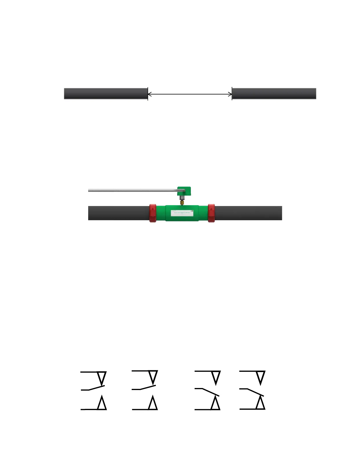
2. At the chosen location in the fire sprinkler piping remove an eighteen (18) inch pipe section from
the fire sprinkler system.
3. Roll groove the remaining ends of the fire sprinkler system piping to receive a standard
mechanical coupling.
4. Install the In-Line Corrosion Detector of matching pipe material, diameter and schedule into the
section space that has been created with the removal of the eighteen (18) inch pipe section.
Orient the In-Line Corrosion Detector so that the pressure switch is accessible for maintenance.
Tighten the mechanical couplings as per the manufacturer’s specifications.
5. (Optional) Connect the wiring from the monitoring system to the pressure switch (dry contact) in
accordance with the manufacturer’s wiring instructions. Activation of the In-Line Corrosion
Detector should be identified as a supervisory signal.
Detector Remote Test Station Installation Instructions
1. The Detector Remote Test Station mounts to a 2” x 4” x 2⅛” minimum depth handy box
(Raco model 670RAC or approved equal) in an accessible location near the In-Line Corrosion
Detector.
2. Recommended mounting height 72” AFF.
3. Connect 2-conductor, in accordance with applicable national and/or local codes
(i.e., NFPA 70), between the In-Line Detector and the Remote Test Station (recommended
18 AWG cable).
NOTE: The conduit/cabling must enter through the top or bottom knockout of the 2” x 4” handy
box.
4. Provide any required raceway or mechanical protection, as required.
5. Connect the terminals of the Remote Station to the common (COM) and normally open (A) of the
pressure switch.
Model EPS10-2 Pressure Switch Electrical Connections
 Loading...