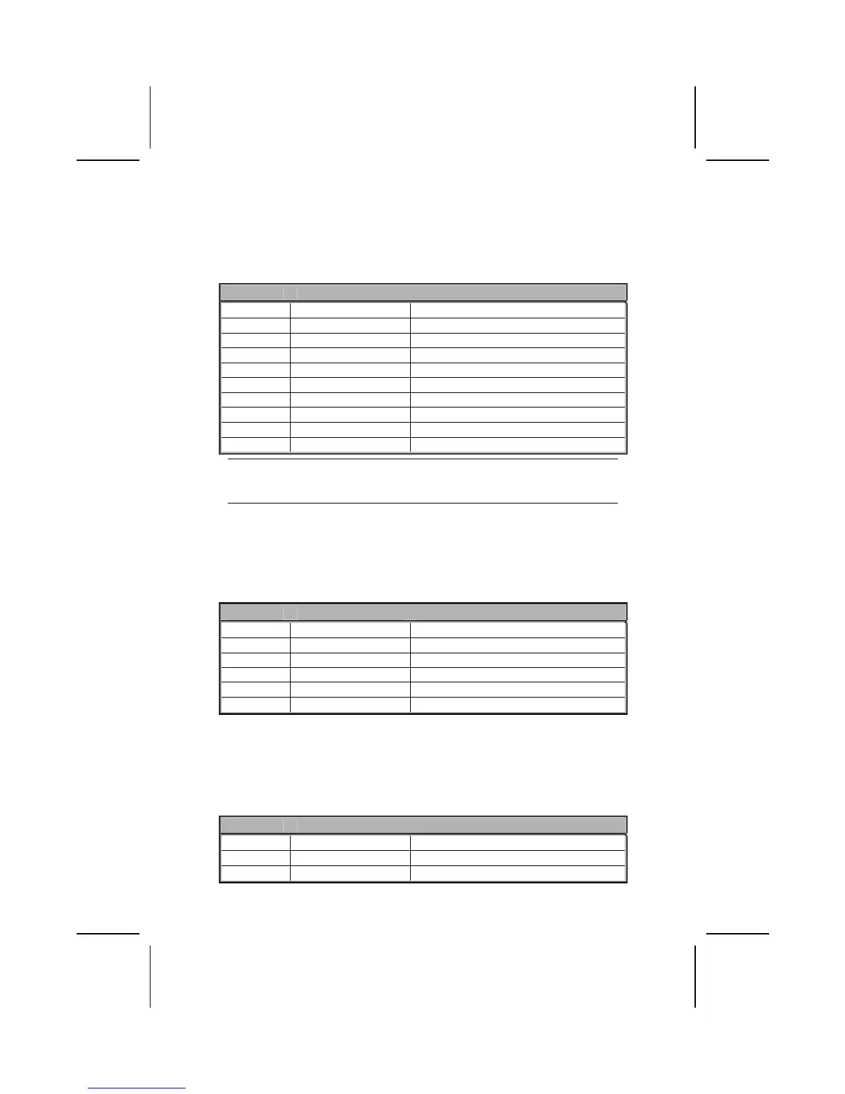
USB2/USB3: Front panel USB ports
The mainboard has two USB ports installed on the rear edge I/O port array.
Additionally, some computer cases have USB ports at the front of the case. If
you have this kind of case, use auxiliary USB connectors USB2 and USB3 to
connect the front-mounted ports to the mainboard.
Pin Signal Name Function
1 VREG_FP_USBPWR0 Front Panel USB Power
2 VREG_FP_USBPWR0 Front Panel USB Power
3 USB_FP_P0- USB Port 0 Negative Signal
4 USB_FP_P1- USB Port 1 Negative Signal
5 USB_FP_P0+ USB Port 0 Positive Signal
6 USB_FP_P1+ USB Port 1 Positive Signal
7 GND Ground
8 GND Ground
9 KEY No pin
10 USB_FP_OC0 Overcurrent signal
Note: Please make sure that the USB cable has the same pin assignment as indi-
cated above. A different pin assignment may cause damage or system
hang-up.
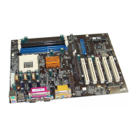
SIR1: Serial infrared port
The mainboard supports a Infrared (IR1) data port. Infrared ports allow the
wireless exchange of information between your computer and similarly
equipped devices such as printers, laptops, Personal Digital Assistants
(PDAs), and other computers.
Pin Signal Name Function
1 Not assigned Not assigned
2 KEY No pin
3 +5V IR Power
4 GND Ground
5 IRTX IrDA serial output
6 IRRX IrDA serial input
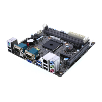
WOL1: Wake On LAN
If you have installed a LAN card, use the cable provided with the card to plug
into the mainboard WOL1 connector. This enables the Wake On LAN (WOL1)
feature. When your system is in a power-saving mode, any LAN signal auto-
matically resumes the system. You must enable this item using the Power
Management page of the Setup Utility.
Pin Signal Name Function
1 5VSB +5V stand by power
2 GND Ground
3 Ring# Wake up signal (high active)
22