12
Installing the Motherboard
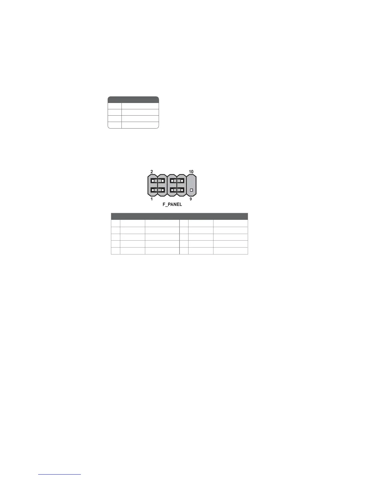
Front Panel Header
The front panel header (F_PANEL) provides a standard set of switch and LED
headers commonly found on ATX or Micro ATX cases. Refer to the table below for
information:
Power/Sleep/Message waiting LED
Connecting pins 2 and 4 to a single or dual-color, front panel mounted LED provides
power on/off, sleep, and message waiting indication.
Hard Drive Activity LED
Connecting pins 1 and 3 to a front panel mounted LED provides visual indication
that data is being read from or written to the hard drive. For the LED to function
properly, an IDE drive should be connected to the onboard IDE interface. The LED
will also show activity for devices connected to the SCSI (hard drive activity LED)
connector.
Pin Signal Function Pin Signal Function
1 HD_LED_P Hard disk LED (+)
2 FP PWR/SLP *MSG LED (+)
3 HD_LED_N Hard disk LED (-)
5 RST_SW_N Reset Switch (-)
7 RST_SW_P Reset Switch (+)
9 RSVD Reserved
4 FP PWR/SLP *MSG LED (-)
6 PWR_SW_P Power Switch (+)
8 PWR_SW_N Power Switch (-)
10 Key No pin
* MSG LED (dual color or single color)
SPK: Internal speaker
Pin Signal Name
1 VCC
2 Key
3 NC
4 Signal
 Loading...