17
Chapter 2: Motherboard Installation
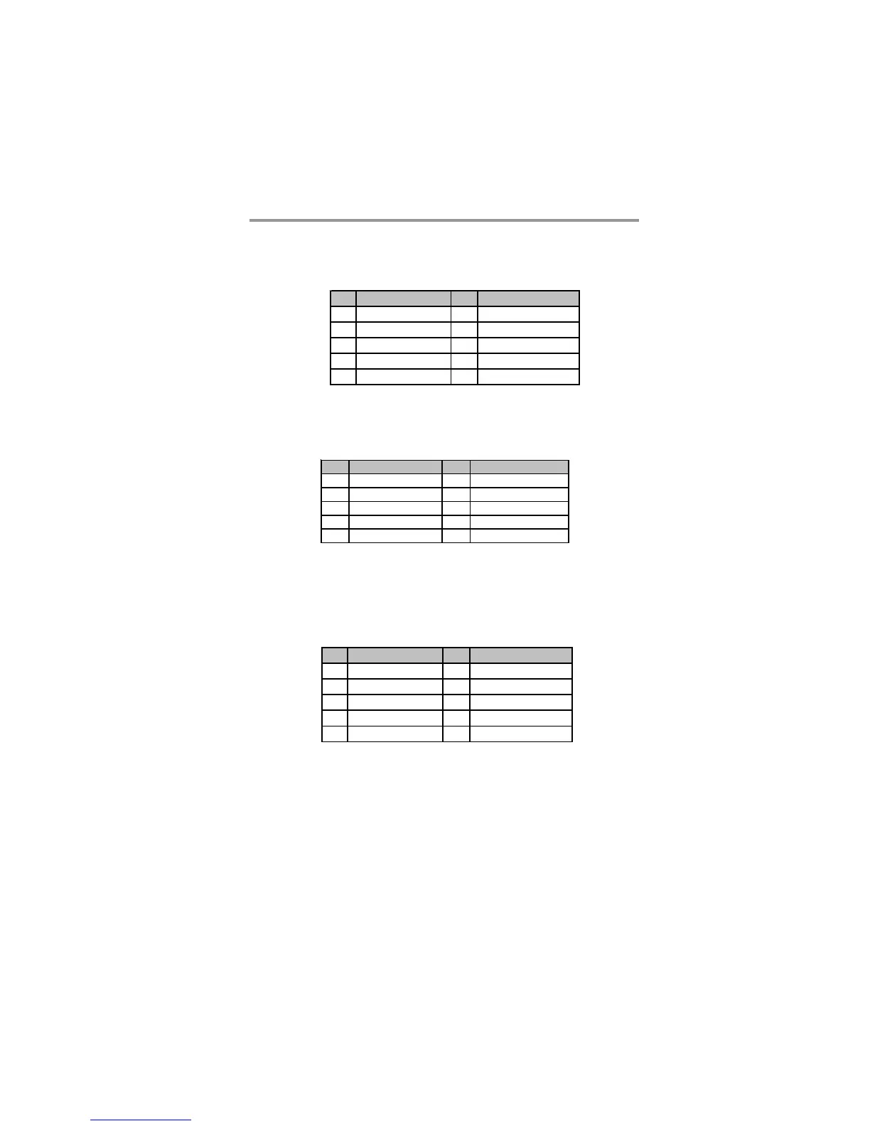
F_AUDIO: Front Panel Audio Header
This header allows the user to install auxiliary front-oriented microphone and line-
out ports for easier access.
Pin Signal Pin Signal
1PORT1L 2GND
3 PORT1 R 4 PRESENCE#
5 PORT2R 6 Sense1_return
7 SENSE_ SEND 8 K EY
9PORT2L 10Sense2_return
Pin Signal Pin Signal
1USBPWR0 2USBPWR1
3 USB_ FP_P0 ( - ) 4 USB_FP_ P1( - )
5 USB_FP_P0(+) 6 USB_FP_P1(+)
7 GROUND 8 GROUND
9KEY 10NC
1. Locate the F_USB header on the motherboard.
2. Plug the bracket cable onto the F_USB header.
3. Remove a slot cover from one of the expansion slots on the system
chassis. Install an extension bracket in the opening. Secure the extension
bracket to the chassis with a screw.
F_USB1~2: Front Panel USB Header
The motherboard has four USB ports installed on the rear edge I/O port array.
Additionally
, some computer cases have USB ports at the front of the case. If you
have this kind of case, use auxiliary USB header F_USB to connect the front-
mounted ports to the motherboard.
Pin Signal Pin Signal
1 DCDB 2 SINB
3SOUTB 4DTRB
5GND 6DSRB
7RTSB 8CTSB
9RI 10KEY
COM: Onboard Serial Port Header
Connect a serial port extension bracket to this header to add a second serial port to
your system.
 Loading...