15
Chapter 2: Motherboard Installation
Pin Signal Pin Signal
1 HD_LED_P(+) 2 FP PWR/SLP(+)
3 HD_LED_N(-) 4 FP PWR/SLP(-)
5 RES ET_ SW_N( - ) 6 POWER_SW_P( +)
7 RES ET_ SW_P( +) 8 POWER_S W_N( - )
9 RSV D_DNU 10 KEY
Here is a list of the F_PANEL pin assignments.
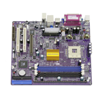
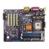
Install the Motherboard
Install the motherboard in a system chassis (case). The board is a Micro ATX size
motherboard. You can install this motherboard in an ATX case. Make sure your
case has an I/O cover plate matching the ports on this motherboard.
Install the motherboard in a case. Follow the case manufacturer’s instructions to
use the hardware and internal mounting points on the chassis.
Connect the power connector from the power supply to the ATX_POWER
connector on the motherboard. The ATX12V is a +12V connector for CPU Vcore
power.
If there is a cooling fan installed in the system chassis, connect the cable from the
cooling fan to the CPU_FAN fan power connector on the motherboard.
Connect the case switches and indicator LEDs to the F_PANEL header.
 Loading...