Quick Start Guide
– 3 –
3. Ground the Switch Before powering on the switch, ground the switch to earth.
Ensure the rack on which the switch is to be mounted is properly grounded and in
compliance with ETSI ETS 300 253. Verify that there is a good electrical connection
to the grounding point on the rack (no paint or isolating surface treatment).
Caution:
The earth connection must not be removed unless all supply
connections have been disconnected.
4. Connect Power Connect the switch to an AC power source to power on. Verify that the external AC
power requirements for the switch can be met as listed below:
ECS2100-10T: AC 100-240 V, 50-60 Hz, 0.5 A
ECS2100-10P: AC 100-240 V, 50-60 Hz, 2.1 A
ECS2100-28T: AC 100-240 V, 50-60 Hz, 0.5 A
ECS2100-28P: AC 100-240 V, 50-60 Hz, 3.2 A
ECS2100-28PP: AC 100-240 V, 50-60 Hz, 5.8 A
Caution:
Before connecting the switch to AC power, the grounding terminal screw
on the switch rear panel must be connected to earth.
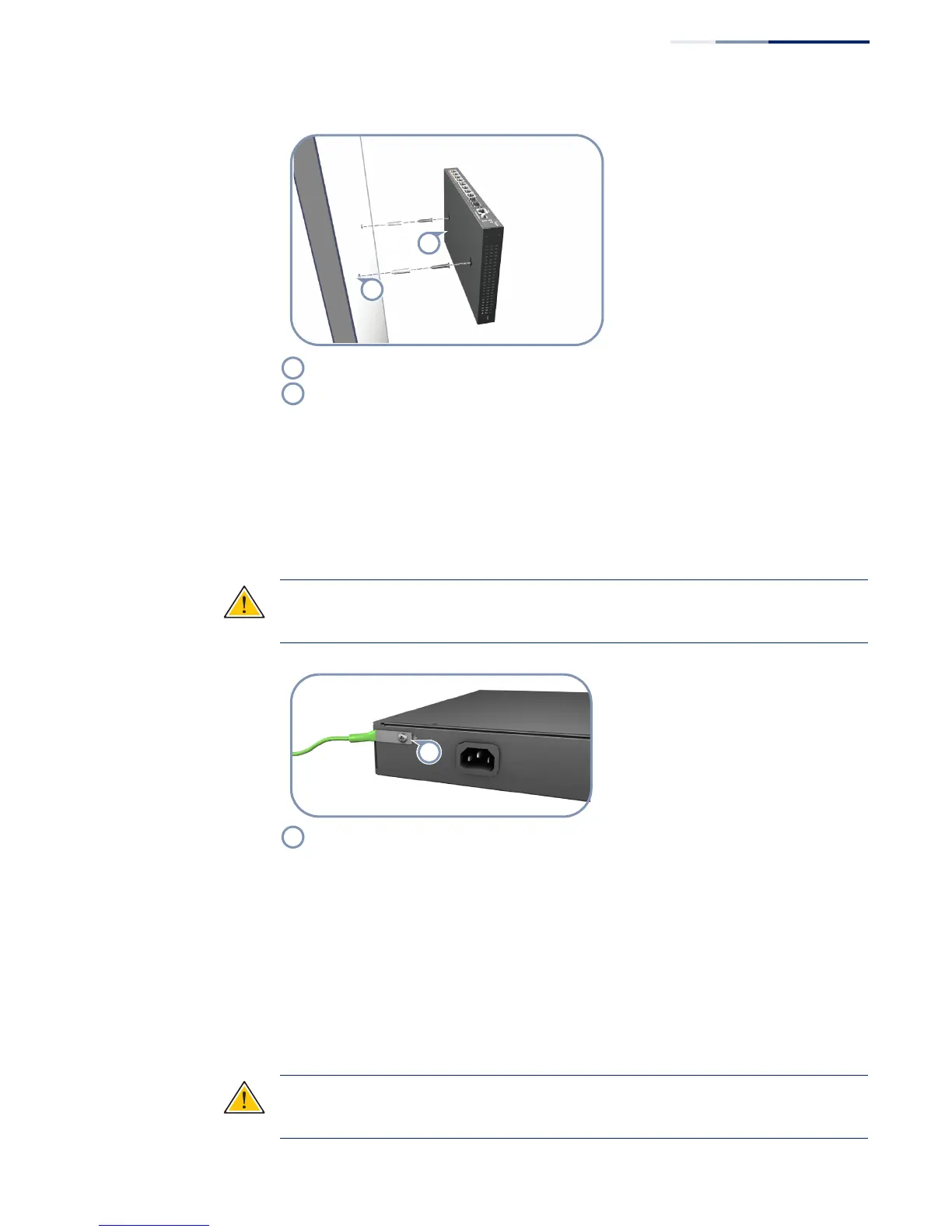
Set two screws in the wall 150 mm (5.9 in.) apart.
Slide the switch’s wall mounting slots down onto the screws so that the unit is secure.
Connect a grounding wire and lug to the grounding point on the switch rear panel, and then
to rack ground.

 Loading...