Chapter 1
| Switch Description
Overview
– 14 –
Console Port
The RJ-45 connector on the front panel labeled “Console” provides an out-of-band
serial connection to a terminal or a PC running terminal emulation software. The
port can be used for performing switch monitoring and configuration. For more
information, see “How to Connect to the Console Port” on page 52.
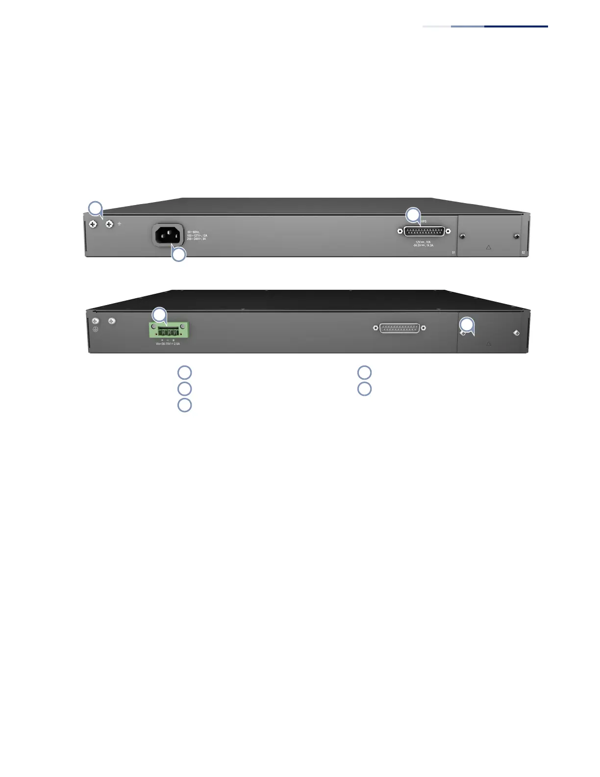
Figure 2: Rear Panel
Grounding Terminal
The switch includes a grounding terminal that must be connected to a ground
source that provides local earth potential. For more information, see “Grounding
the Chassis” on page 33.
RPS Connector
The switch supports an optional Redundant Power Supply (RPS), that can supply
power to the switch in the event the internal power supply fails. For more
information, see “DC Power Supply” on page 32.
Expansion Module Slot
The switch includes one slot on the rear panel for a hot-swappable dual-port
10GBASE module. For more information, see “Optional Media Expansion Module”
on page 29.
AC Power Socket
The switch requires a 100-240 VAC, 50-60 Hz AC power source. For more
information on the switch power input, how to connect it, and how to power-on
the switch, see “How to Connect to AC Power” on page 34.
Grounding Terminal Expansion Module Slot
RPS Connector DC Power Socket
AC Power Socket
 Loading...