Chapter 4
| Power and Grounding
How to Connect to DC Power
– 36 –
To connect the switch to a power source:
1. Verify that the external DC power supply can provide 36 to 75 VDC, 3.82 A
maximum.
2. Prepare two wires for the DC power source. Use 10 to 18 AWG stranded copper
wire. Make sure these wires are not plugged into the power source.
3. Use a wire stripper to carefully strip about a half an inch of the outer insulation
off the end of each wire, exposing the copper core.
4. Twist the copper wire strands together to form a tight braid. If possible, solder
the exposed braid of wire together for better conductivity.
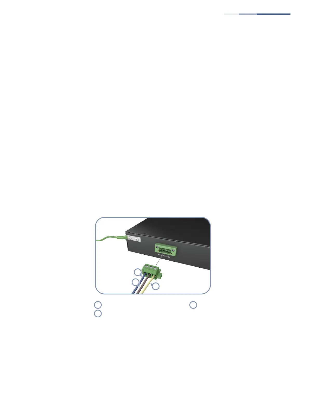
5. Connect the external power feed and power ground/return lines to the DC plug
(provided with the switch) as shown in Figure 21. The brown wire connects to
the “-” pin, and the blue wire to the “+” pin. Use a small flat-tip screwdriver to
loosen the screws on the power plug and open the wire clamps.
Insert the wire leads into the openings shown in Figure 21. Each lead inserted
in the power plug must match the lead attached to the power source. Use the
label on the DC power connection block to identify the appropriate power
input and return or ground lines.
Figure 21: DC Plug Connections
VDC (blue wire) Chassis Ground (yellow-green wire)
VDC Return (brown wire)
 Loading...