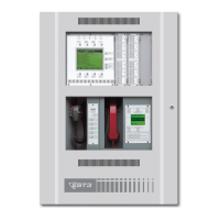
Operations Manual 1
CM1(N) Operation
Controls and Indicators
NORMAL
ALARM
SUPERVISORY
TROUBLE
SILENCE
TROUBLE
SILENCE
BACK
TEST/PRGM
RESET
ALARM
NEXT/ACK
DRILL/
ALL CALL
1
10
11
12
13
14
15
16
17
18
19
2
3
4
5
6
7
8
9
[OP-001.CDR]
LED Indicators (call-outs 1 - 5)
The CM1(N) master controller provides five LEDs to indicate Normal,
Alarm, Supervisory, and Trouble conditions and Test/Program mode.
CM1(N) LED Indicators
LED Indicator Color Description
Normal Green Normal system/panel operation.
Alarm Red Alarm condition. Buzzer pulsates.
Supervisory Yellow Short on a supervisory zone. Remains
ON until short is cleared.
Trouble Yellow Open on a supervisory zone. Remains
ON until cleared and/or system is reset.
Test/Prgm Yellow System in test/program mode.
Combination Switch / LEDs (call-outs 6 - 9)
The CM1(N) master controller provides four switch/LEDs that perform
the following functions:
CM1(N) Switch / LEDs
Switch / LED Description
Reset Reset panel/system. Pressing this switch calls the
predetermined action 9002.
Alarm Silence Silences audible devices. Yellow LED on switch
illuminates, indicating audible devices have been
silenced. If subsequent alarms are received, the