Operations Manual 21
CM2N Operation
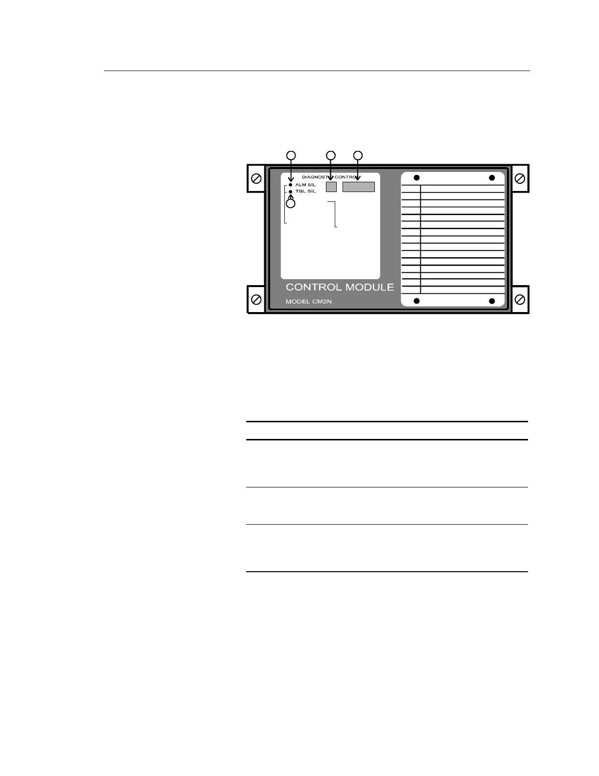
Controls and Indicators
134
ZONE DIRECTORY
ZONE #
ZONE LOCATION
To R E SE T, pu sh
both switches
simultaneously
ZONE/DEVICE
1. FIRE ALARM
2. SUP. OPEN
3. SUP SHORT
4. SENSOR ALERT
P. INTERNAL
P 001 = 24 Vdc output #1 or #2 fail
P 002 = Ground fault
P 003 = AC power fail
P 004 = PS Internal voltage trouble
P 005 = Battery or charger trouble
P 006 = City box/Mic trouble
P 007 = ZAS card fail/continuity
P 008 = Printer fail
P 009 = Alarm Silence
P 010 = Trouble Silence
P 011 = Communications fail
CODE
[OP-002.CDR]
2
Switches (call-outs 1 and 2)
The CM2N secondary network controller is slaved to the CM1N, and
does not require extensive operator action. The CM2N provides two
switches used for Alarm Silence, Trouble Silence, and Reset functions.
CM2N Switches
Switch Description
Alarm Silence
(action 9004)
Silences all audible device circuits connected to
the CM2N. This switch is active only when the
CM2N is in standalone mode (P011 is
displayed).
Trouble Silence Silences the trouble buzzer in the power supply
associated with the CM2N. This switch is active
only when the CM2N is in standalone mode.
Reset (Alarm
Silence + Trouble
Silence)
Resets the CM2N. Reset is accomplished by
operating both the ALM SIL and TBL SIL
switches simultaneously. This function is active
only when the CM2N is in standalone mode.
Code Window (call-out 3)
The CM2N front panel 7-segment LED displays are divided into two
windows. The readout in the CODE window indicates the nature of the
alarm.