22 Operations Manual
CODE Window Display
CODE Display Description
1 Fire Alarm
2 Trouble
3 Supervisory Short
4 Sensor Alert
P Internal Fault
Zone/Device Window (call-out 4)
The readout in the Zone/Device window indicates the panel address
associated with the number displayed in the Code window. To interpret
the Zone/Device display when the Code window displays a 0, 1, 2, or
3, you must know which cards are installed in the CM2N.
Note: When both the Code and Zone/Device windows read “0000,” the
programming switch is in the ON position.
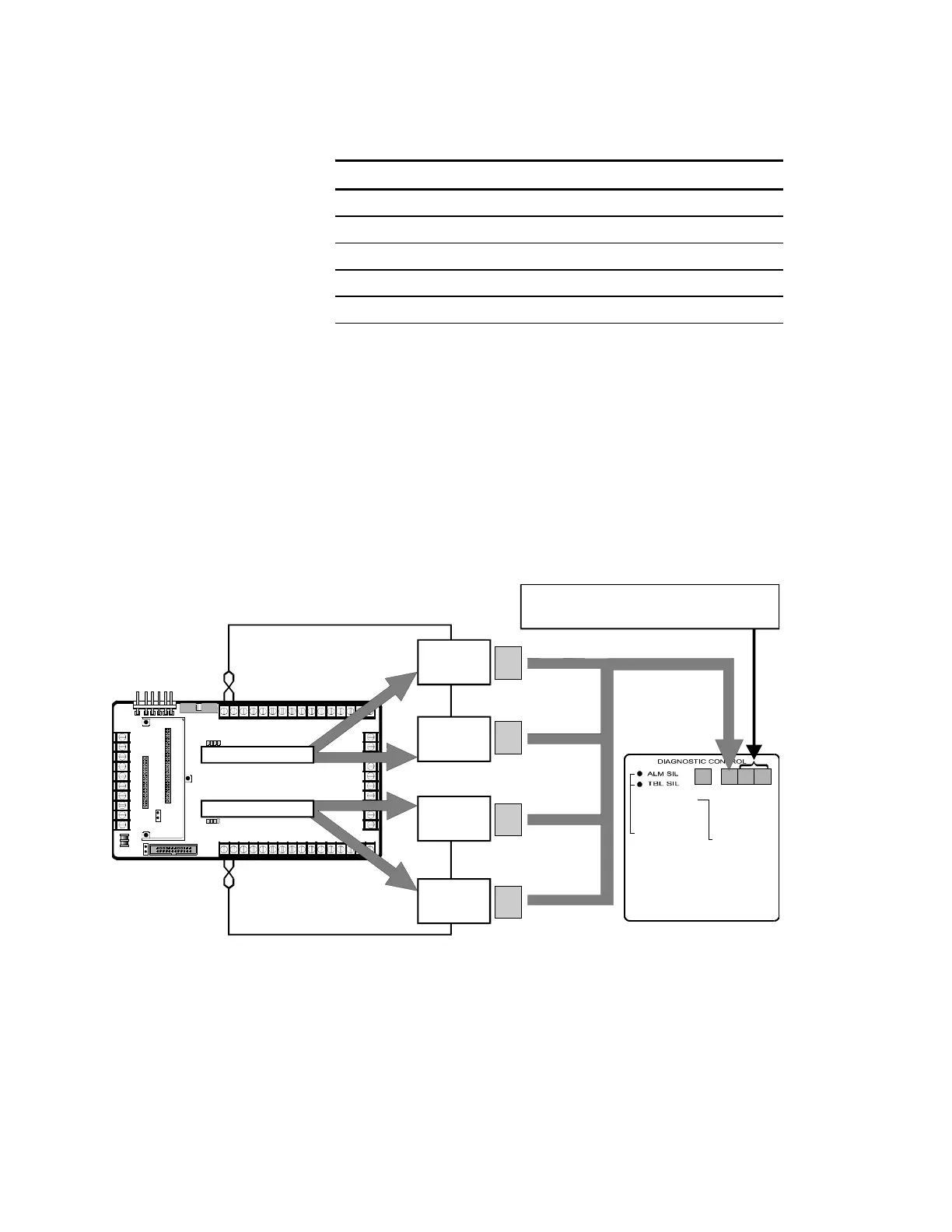
The following figure shows how to interpret the Zone/Device display
when two ZAS-1 Cards are installed in the CM2N control panel
motherboard.
[OP-003.CDR]
TB4
TB2
TB3
TB1
1
4
4
8
8
10
10
1
1
5
5
3
3
7
7
9
9
2
2
6
6
1
9
9
5
5
13
13
3
3
11
11
7
7
15
15
2
2
10
10
6
6
14
14
4
4
12
12
8
8
16
16
P1
P2
P3
P4
P7
J1
J2
CM2N Control Panel
Motherboard
M2N
n
l M
l
To RESET, push
both switches
simultaneously
ZONE/ DEVICE
1. FIRE ALARM
2. SUP. OPEN
3. SUP SHORT
4. SENSOR ALERT
P. INTERNAL
P 001 = 24 Vdc output #1 or #2 fail
P 002 = Ground fault
P 003 = AC power fail
P 004 = PS Internal voltage trouble
P 005 = Battery or charger trouble
P 006 = City box/Mic trouble
P 007 = ZAS card fail/continuity
P 008 = Printer fail
P 009 = Alarm Silence
P 010 = Trouble Silence
P 011 = Communications fail
CODE
0
1
2
3
ZAS-1 CARD
ZAS-1 CARD
0
1
2
Sensors
For ZAS-1 Card (Top Slot), display = 01 thru 96
For ZAS-1 Card (Bottom Slot), display = 01 thru 96
Sensors
Modules
Modules
Two ZAS-1 Cards Installed
The following figure shows how to interpret the Zone/Device display
when one ZAS-1 Card and one Traditional Card is installed in the
CM2N control panel motherboard.