Operations Manual 23
[OP-004.CDR]
TB4
TB2
TB3
TB1
1
4
4
8
8
10
10
1
1
5
5
3
3
7
7
9
9
2
2
6
6
1
9
9
5
5
13
13
3
3
11
11
7
7
15
15
2
2
10
10
6
6
14
14
4
4
12
12
8
8
16
16
P1
P2
P3
P4
P7
J1
J2
CM2N Control Panel
Motherboard
CM2N Cont
ol Module
To R ES ET, pu sh
both switches
simultaneously
ZONE/DEVICE
1. FIRE ALARM
2. SUP. OPEN
3. SUP SHORT
4. SENSOR ALERT
P. I NTERNAL
P 001 = 24 Vdc output #1 or #2 fail
P 002 = Ground fault
P 003 = AC power fail
P 004 = PS Internal voltage trouble
P 005 = Battery or charger trouble
P 006 = City box/Mic trouble
P 007 = ZAS card fail/continuity
P 008 = Printer fail
P 009 = Alarm Silence
P 010 = Trouble Silence
P 011 = Communications fail
CODE
0
1
2
ZAS-1 CARD
Sensors
Modules
Zones
Traditional CARD
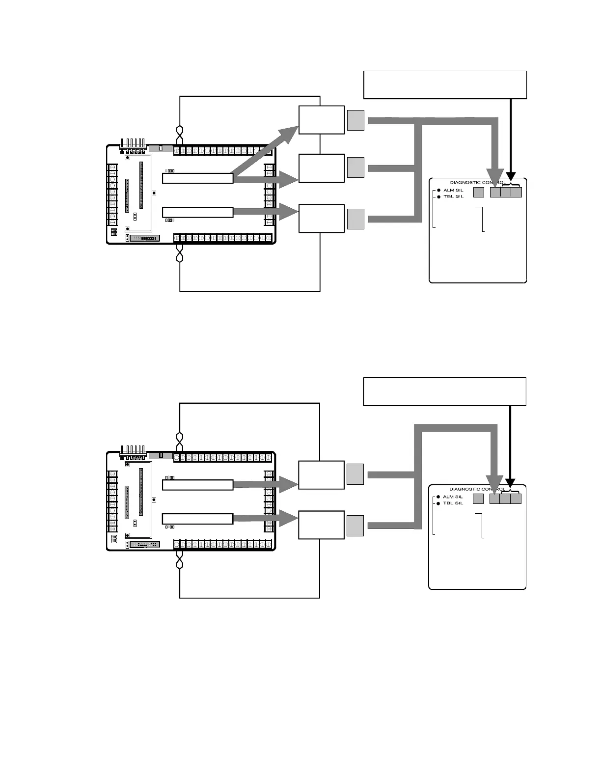
For ZAS-1 Card (Top Slot), display = 01 thru 96
For Traditional Card (Bottom Slot), display = 01 thru 08
One ZAS-1 Card and One Traditional Card Installed
The figure bellow shows how to interpret the Zone/Device display
when two Traditional Cards are installed in the CM2N control panel
motherboard.
[OP-005.CDR]
TB4
TB2
TB3
TB1
1
4
4
8
8
10
10
1
1
5
5
3
3
7
7
9
9
2
2
6
6
1
9
9
5
5
13
13
3
3
11
11
7
7
15
15
2
2
10
10
6
6
14
14
4
4
12
12
8
8
16
16
P1
P2
P3
P4
P7
J1
J2
CM2N Control Panel
Motherboard
M2N
n
lM
l
To RESET, push
both switches
simultaneously
ZONE/DEVICE
1. FIRE ALARM
2. SUP. OPEN
3. SUP SHORT
4. SENSOR ALERT
P. INTERNAL
P 001 = 24 Vdc output #1 or #2 fail
P 002 = Ground fault
P 003 = AC power fail
P 004 = PS Internal voltage trouble
P 005 = Battery or charger trouble
P 006 = City box/Mic trouble
P 007 = ZAS card fail/continuity
P 008 = Printer fail
P 009 = Alarm Silence
P 010 = Trouble Silence
CODE
0
0
Zones
Zones
Traditional CARD
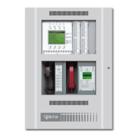
For Traditional Card (Top Slot), display = 01 thru 08
For Traditional Card (Bottom Slot), display = 49 thru 56
Traditional CARD
Two Traditional Cards Installed
The following figure shows how to interpret the Zone/Device display
when two ZAS-2 Cards are installed in the CM2N control panel
motherboard.