Edwards and the Edwards logo are trademarks of Edwards Limited.
1. External electrical supply
2. Earth (ground)
3. Electrical supply connector
4. Electrical supply isolator
5. Front panel Heater switch *
6. Bakeout band fuse *
7. Rear panel bakeout band connector *
8. Bakeout band *
9. Backing pump
10.Backing pump relay *
11.Rear panel backing pump relay connector *
12.Rear panel Active gauge connector
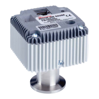
13.Active gauge
14.Speed indicator
15.Logic interface connector
16.External SYS Interlock switch
17.External TMP Interlock switch
18.External Remote Standby switch
19.External Remote Start/Stop switch
20.TMP Normal output (normally open)
21.TMP Fail output (normally closed)
22.Not used
23.Vent-valve
24.Air-cooler
25.Remote indicator equipment
A. Vacuum and control system
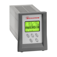
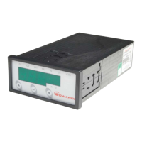
B. EXC Controller
L. Live electrical supply
N. Neutral electrical supply
E. Earth (ground) electrical supply
* Not available on the EXC120E Controller.
 Loading...