1. External electrical supply
2. Earth (ground)
3. Electrical supply connector
4. Electrical supply isolator
5. Front panel Heater switch
6. Bakeout band fuse
7. Rear panel bakeout band connector
8. Bakeout band
9. Backing pump
10.Backing pump relay
11.Rear panel backing pump relay connector
12.Rear panel Active gauge connector
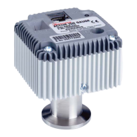
13.Active gauge
14.Speed indicator
15.Logic interface connector
16.External SYS Interlock switch
17.External TMP Interlock switch
18.External Remote Standby switch
19.External Remote Start/Stop switch
20.TMP Normal output (normally open)
21.TMP Fail output (normally closed)
22.Axial Emergency output (normally closed) *
23.Vent-valve
24.Air-cooler
25.Remote indicator equipment
* EXC300M Controller only.
A. Vacuum and control system
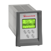
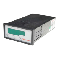
B. EXC Controller
L. Live electrical supply
N. Neutral electrical supply
E. Earth (ground) electrical supply