The pneumac regulator is pre-set to 50 ± 5 psig in the factory and does not need to be
adjusted. The pneumac regulator is shown in Figure: DP clean assembly for the pump
only systems, item 5 for the pump‑only systems. For pump and booster combinaon
systems, the regulator is contained within the pump enclosure.
To use an inert gas in place of atmospheric air as the DP clean purge gas, remove the air
lter and in its place connect up the inert gas supply. For pump and booster
combinaons, the air lter is on the rear pump panel (refer to Figure: The controls/
connectors on the rear of the pump (system with rear exhaust and castors/levelling feet
ed), item 12). For pump‑only systems, refer to Figure: DP clean assembly for the pump
only systems, item 1. Refer to DP clean high ow purge/solvent ush opon on page 27
for informaon about ngs and typical purge gas ows.
A solvent sucon pipe is provided with the pump. When only performing a high ow
purge procedure, the solvent sucon pipe will not be needed. When performing a
solvent ush, t the solvent sucon pipe only when ready to perform the DP clean
procedure. For pump and booster combinaons, the solvent ush uid connecon is on
the rear pump panel (refer to Figure: The controls/connectors on the rear of the pump
(system with rear exhaust and castors/levelling feet ed), item 11). For pump‑only
systems, refer to Figure: DP clean assembly for the pump only systems, item 2.
A PDT is required to operate the DP clean high ow purge and solvent ush.
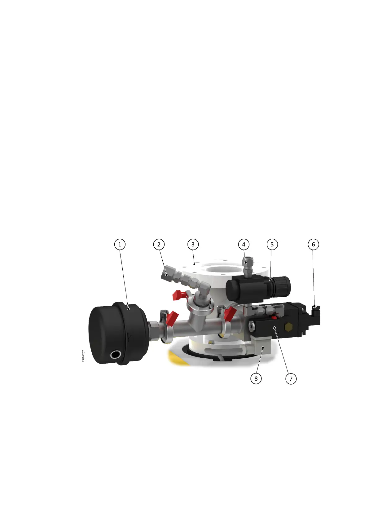
Figure 13 DP clean assembly for the pump only systems
1. Air lter 2. DP clean solvent ush uid connecon
3. Inlet spool 4. Pneumac valve inlet connecon
5. Pneumac regulator 6. Oponal connecon to the pneumac
valve sensor
7. Pneumac valve 8. Pneumac valve electrical connecon
1. Air lter 2. DP clean solvent ush uid connecon
3. Inlet spool 4. Pneumac valve inlet connecon
5. Pneumac regulator 6. Oponal connecon to the pneumac
valve sensor
7. Pneumac valve 8. Pneumac valve electrical connecon
Page 52
M58800880_H - Installaon
 Loading...


