Chapter 2: Installation and configuration
18 LaserSense 100 Aspirating Smoke Detector Installers Handbook
Signal connections
To connect the signal wire:
1. Lead a suitable wire type (RS-485 cable 9841, 120 ohm shielded (screened)
twisted pair or equivalent) through the second cable gland.
2. Tighten it into position with approximately 35 mm (1-1/4 inch) of cable from
the bottom of the cable gland.
3. Remove either the three-way terminal block next to the power supply socket
(if connecting the detector to a SenseNET system) or the four-way Bus
terminal block (if connecting the detector to an alarm panel in conjunction with
the APIC addressable bus card). Refer to Figure 10 below for an illustration of
the terminals and “Setting the detector address” on page 22 for details on
addressing.
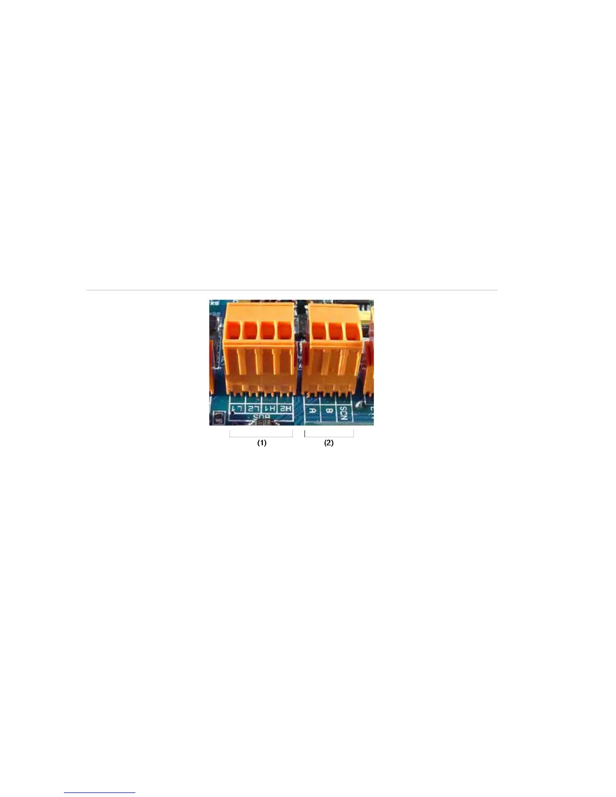
Figure 10: APIC address and RS-485/SenseNET terminals
For example, in a networked system using screened cable, connect the screen
wires to the SCN terminal, Bus A wires to the A terminal and Bus B wires to the B
terminal.
If the detector is in the middle of a networked chain (with input and output
connections) it may be more convenient to link the common Bus A, Bus B, and
screen wires to single A, B and screen wires for linking to the terminal block.
Figure 11 on page 19 shows the power and signal connections to the docking
station for connection to a single network cable.