Chapter 2: Installation and configuration
22 LaserSense 100 Aspirating Smoke Detector Installers Handbook
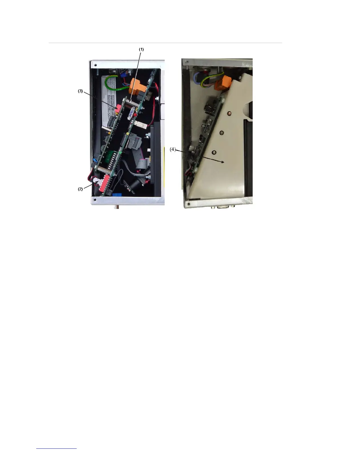
Figure 13: APIC connections (EN/UL certified models)
(1) Mounting studs (4X)
(2) APIC Interface connection
(3) APIC address switch (2X)
(4) Internal cover (UL certified models only)
Setting the detector address
In order to identify itself to the PC command module or fire panel, each detector
needs to have a unique address ranging from 1 to 127. The detector address is
set on DIP switch SW1, at the bottom left of the opened detector on the main
circuit board. The switch settings are up for 1 and down for 0, and the detector
address is set as a 7-bit binary code (switch 8 equates to a value of 128 and so
is outside the usable address range). Refer to Figure 2 on page 5 for the location
of detector DIP switches.
Figure 14 shows a sample DIP switch setting.
The address equates to 11000110 in binary, or:
(1 x 1) + (1 x 2) + (0 x 4) + (0 x 8) + (0x 16) + (1 x 32) + (1 x 64) + (0 x 128) = 99
The full range of available addresses and their relevant switch settings are
provided in Table 3 on page 23 for reference.