© Edwards Limited 2009. All rights reserved. Page 39
Edwards and the Edwards logo are trademarks of Edwards Limited.
Installation
B800-00-880 Issue A
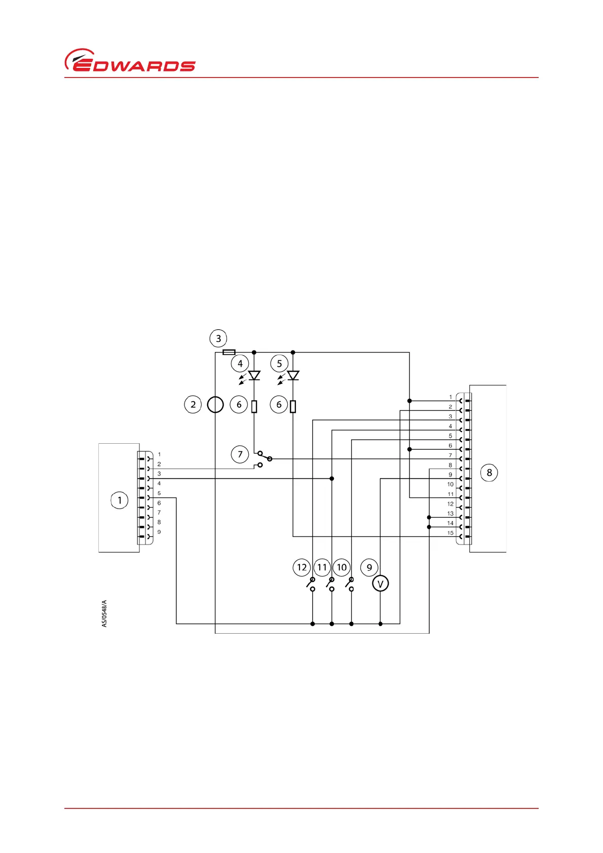
3.7.6 Simultaneous parallel and serial operation
You can control the pump using Parallel Interface control inputs and at the same time monitor various pump
parameters using the Serial Interface. Alternatively you can control the pump using commands sent over the Serial
Interface while at the same time you can monitor the Normal signal and Analogue Output over the Parallel Interface.
Figure 13 shows a schematic diagram of a system that would allow you to do this.
You cannot control the pump using both the Parallel and Serial Interfaces simultaneously. For example, if you start
the pump by sending a Start command over the Serial Interface you cannot then stop the pump by using the Start /
Stop switch on the Parallel Interface. The pump will ignore the state of the Start / Stop switch on the Parallel
Interface. To stop the pump you must send a Serial Stop command. Only when the Serial Stop command has been
received by the pump can any commands sent via the Parallel Interface be acted on.
Similarly, if you Start the pump by using the Start switch on the Parallel Interface you cannot then stop the pump by
sending a Stop command over the Serial Interface. The pump will ignore any Start or Stop commands received over
the Serial Interface. To stop the pump, you must use the Parallel Stop switch. Only when the pump has been stopped
using the Parallel Interface switch will any Start or Stop commands be accepted via the Serial Interface.
Figure 16 - Schematic diagram of the logic interface connections
1. RS232 interface on control equipment
2. 24 V d.c. electrical supply
3. Fuse
4. Optional LED indicator - system OK
5. Optional LED indicator - normal speed
6. Current limit resistor for LED
7. Optional serial mode selector
8. nEXT pump
9. Optional voltmeter
10. Optional serial enable switch
11. Optional standby switch
12. Start switch