Page 3 of 6 DATA SHEET E85001-0609
Not to be used for installation purposes. Issue 1
Installation
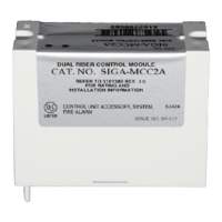
SIGA-MCC2A: mount the UIO motherboard inside a suitable
EDWARDS enclosure with screws and washers provided. Plug the
SIGA-MCC2A into any available position on the motherboard and
secure the module to the motherboard with the captive screws.
Wiring connections are made to the terminals on the motherboard
(see wiring diagram). UIO motherboard terminals are suited for
#12 to #18 AWG (2.5 mm
2
to 0.75 mm
2
) wire size.
#6 Flat washers
6-32
Self-tapping
screws
UIO Motherboard
Plug-in (UIO)
Module
Captive
screws
Cabinet or electrical enclosure
SIGA-CC2A: mount to North American 2-1/2 inch (64 mm) deep
two-gang boxes and 1-1/2 inch (38 mm) deep 4-inch square
boxes with two-gang covers and SIGA-MP mounting plates. The
terminals are suited for #12 to #18 AWG (2.5 mm
2
to 0.75 mm
2
)
wire size.
Electronic Addressing - The loop controller electronically address-
es each module saving valuable time during system commissioning.
Setting complicated switches or dials is not required. Each module
has its own unique serial number stored in its on-board memory.
The loop controller identifies each device on the loop and assigns
a “soft” address to each serial number. If desired, the modules can
be addressed using a laptop computer. No addressing switches are
used.
Warnings & Cautions
These modules do not provide supervision of the riser. The fire
alarm panel must provide this function.
These modules do not support conventional 2-wire smoke detec-
tors.
These modules will not operate without electrical power. As fires
frequently cause power interruption, we suggest you discuss
further safeguards with your fire protection specialist.
EDWARDS recommends that this module be installed according
to latest recognized edition of national and local fire alarm codes.
Compatibility
These modules are part of EDWARDS's Signature Series intel-
ligent processing and control platform. They are compatible with
EST3, EST3X and iO Series control panels.
Testing & Maintenance
The module’s automatic self-diagnosis identifies when it is defec-
tive and causes a trouble message. The user-friendly maintenance
program shows the current state of each module and other perti-
nent messages. Single modules may be turned off (de-activated)
temporarily, from the control panel.
Scheduled maintenance (Regular or Selected) for proper system
operation should be planned to meet the requirements of the
Authority Having Jurisdiction (AHJ). Refer to current NFPA 72 and
ULC CAN/ULC 536 standards.